| Contents | Previous | Post Test |
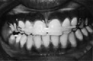
Spacing between the anterior teeth may be caused by a variety of factors. The upper incisor teeth may be protruded due to a hyperactive tongue, hypotonic perioral musculature, discrepancies between tooth size and dental arch length, an abnormally large frenum, or ectopic tooth eruption.
Several types of orthodontic appliances may be utilized in the treatment of protruded anterior teeth, one of which is a removable appliance utilizing elastic traction. Elastic therapy or forces generated by the activation of labial wires can be used with removable appliance techniques, depending on whether a continuous or an intermittent force is desired. Either technique is satisfactory, as long as the forces are within the limits necessary for efficient tooth movement.
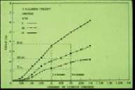
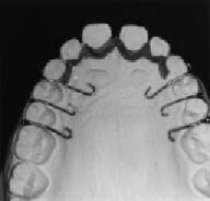
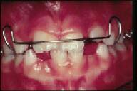
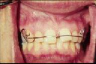
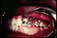
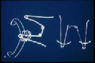
A light elastic is often attached between two hooks situated on the labial surface of the canine teeth (Figure 116) The elastic should be relatively light, producing no more than 3 1/2 ounces of force at maximum activation. Generally speaking, the elastic will produce the force established by the manufacturer when it is stretched to two times the original diameter of the lumen.(26) (Figure 117) The patient is supplied with sufficient elastics to last for two weeks, during which time they are replaced every one or two days.
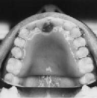
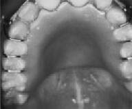
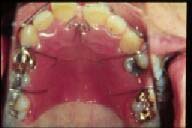
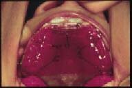
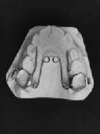
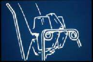
Care must be taken not to remove an excessive amount of palatal acrylic behind the anterior teeth during treatment, since it may cause tissue irritation as the gingiva is pinched between the moving teeth and acrylic. (Figure 118) Therefore, no more than 1 to 2 millimeters of acrylic should be removed in any one visit in order to prevent this complication from occurring. (Figure 119) Prior to fabricating the removable orthodontic appliance, it is advisable to place a small amount of wax palatal or lingual to the anterior teeth to be moved. (Figure 120) This will allow enough space for the teeth to move distally without impinging on the palatal or lingual tissue.
|
|
| Figure 116. Labial elastic used to retracted upper incisors. | Figure 117. Graph shows how required force is produced when elastics are stretched to two times their original lumen size. |
|
|
| Figure 118. When excessive palatal acrylic is removed, gingiva is pinched as teeth move causing irritation. | Figure 119. Only a small amount of palatal acrylic should be removed prior to activation. |
|
Figure 120. Prior to fabricating the appliance, place wax palatal to the anterior teeth. |
A controversy sometimes arises as to what causes a midline diastema, or the space between the maxillary central incisors. Some say that the pressure of a labial frenum produces a diastema, while others report that the frenum is present because the incisors have not come together to produce sufficient pressure for resorption.
Some spacing is normal prior to the eruption of the permanent canines. This is the transient malocclusion referred to as the “ugly duckling” stage of dental development.(27) As described previously, when the canines erupt the pressure of eruption causes an autonomous uprighting of the lateral incisors, space closure, and frenum resorption.(10) Therefore, if sufficient space is present for the permanent canines, any anterior space closure should be minimal or postponed until after these teeth erupt. If overzealous treatment is performed too early, there is a possibility of incisor root resorption or distal deflection of the canine teeth from their normal path of eruption.
If the teeth adjacent to the diastema are parallel, or if the crowns are tipped toward the space, then a banded approach with a segmented or sectional arch wire is necessary. (Figures 121 & 122) The wire helps to upright the teeth and moves the crowns together so that the teeth parallel each other. This will prevent relapse and periodontal problems.
An “active” Hawley type of removable orthodontic appliance, either with a labial wire or an elastic, may also be utilized to aid in the closure of a diastema. By the term “active,” the author wants to differentiate this tooth-moving Hawley appliance from the “passive” Hawley appliance which retains the teeth after orthodontic therapy. If there is also anterior protrusion of the incisors, causing an excessive incisor horizontal overlap (“overjet”), activation of the Hawley appliance will move the incisors palatally.
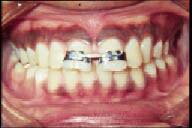
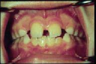
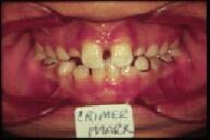
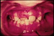
Figures 123 and 124 illustrate a case where there was a diastema between the maxillary central incisors, along with protrusion of these two teeth. An active Hawley appliance was utilized to retract the teeth toward the palate, and helical loop springs were activated to move the teeth mesially to close the midline diastema, and to open sufficient space for the eruption of the permanent upper lateral incisors.
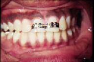
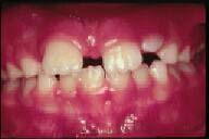
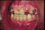
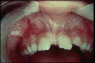
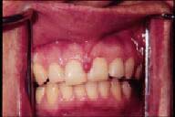
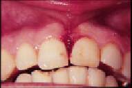
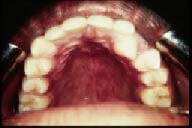
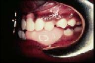
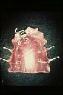
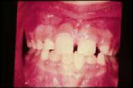
Figure 125 shows a similar case of maxillary incisor protrusion with a maxillary midline diastema. The protrusion, however, was more severe than the previously shown case, and a Hawley removable orthodontic appliance was activated to retract the maxillary central incisors. Figure 126 illustrates an auxiliary spring soldered to the labial wire of the Hawley appliance in order to guide the maxillary right lateral incisor along its proper path of eruption. Figure 127 shows the labial “bulge” of the erupting maxillary left lateral incisor. Another auxiliary spring was eventually soldered to the Hawley labial wire to perform the same tooth guidance that was used on the maxillary right lateral incisor. This case is a good example of limited interceptive and corrective orthodontic therapy to treat an “incipient” malocclusion.
 |
 |
| Figure 121. Closing an anterior diastema with a limited banding technique. Sectional arch wire with elastic therapy. | Figure 122. Sectional wire moves teeth together in a parallel manner. |
 |
 |
| Figure 123. Incisor protrusion with midline diastema. | Figure 124. Hawley appliance with helical loop springs retracted incisors and closed diastema. |
 |
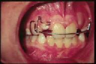 |
| Figure 125. Central incisors protruded with diastema prior to eruption of lateral incisors. | Figure 126. Auxiliary spring soldered to labial wire to guide the eruption of upper right lateral incisor. |
It is important for the clinician to be cognizant of the sequence of eruption of the permanent teeth, especially the canines and premolars, and how it differs between the maxillary and mandibular dental arches.(10) As a review, the canines erupt after the first and second premolars in the maxillary dental arch, but prior to the premolars in the mandibular dentition. This is the reason why the canines are more likely to be impacted in the upper dental arch, and why the second premolars are usually the teeth impacted in the mandibular dentition if a lack of space exists during the sequence of eruption.(28) Although there are numerous theories of tooth eruption, the author feels that the most viable one is the formation of the root and how this causes the tooth to move toward the oral cavity. A tooth should be “ready to erupt” when 2/3 to 3/4 of its root has formed. Once the root has fully developed, then it is said that it has lost its “erupting potential.” The next case to be illustrated is a perfect example of a clinician utilizing this theory of tooth eruption, and preventing tooth impaction.
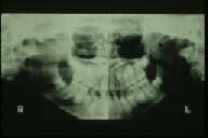
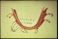
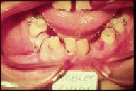
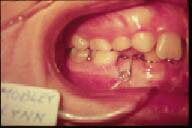
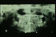
Figure 128 reveals a panorex radiograph of a patient whose mandibular canine/premolar eruption pattern had been disrupted, especially on the right side of the dental arch due to the distal movement of the lower incisors. Note the development of the canine roots, and the fact that the lower right canine is below the eruption pattern of the premolars on that side of the dental arch. If no treatment had been instituted at this time, this canine would certainly have become impacted. It should also be noted that the patient had a congenitally missing lower incisor, which was the likely cause of the mandibular incisor “drifting.” Figure 129 illustrates the type of mandibular removable orthodontic appliance that was used for the majority of the tooth movement procedures. It consisted of various helical loop finger springs to move the incisors toward the midline creating space for the mandibular canines to erupt. Note the double helical coil on the right side of the appliance. It was constructed in this manner to increase the amount of wire in the finger spring to allow for a more continuous force on the lower right incisors. Figures 130 through 132 show the appliance in place and activated, as well as the tooth movement that occurred following the activation of the helical loop finger springs. Figure 133 illustrates a panorex radiograph revealing the space that was opened by the treatment and the eruption pattern of the lower right canine. Figures 134 and 135 show the normal positioning of the lower canines and premolars after removable orthodontic appliance therapy. Treatment was continued, in this case with a lower 0.016" X 0.016" “utility arch wire” to intrude the incisors and correct the anterior deep overbite (incisor vertical overlap). The author feels that the general dentist should be capable of performing the treatment utilizing the removable orthodontic appliance, and that the “2nd half” of the treatment could very well be referred to an orthodontic specialist, noting the complexity of the case. This is a good example of inter-disciplinary “team work,” and how the general dentist is the “watch dog” of the profession, as he or she is usually the first one to see an orthodontic problem and should be the first clinician to diagnose the patient’s situation.
 |
 |
| Figure 127. “Bulging” of left lateral incisor prior to attaching auxiliary spring to guide its eruption. | Figure 128. Panorex radiograph showing lower eruption pattern and drifting of lower incisors. |
 |
 |
| Figure 129. Mandibular removable appliance with helical loop springs to upright incisors. | Figure 130. Helical loop spring after activation. |
 |
 |
| Figure 131. Mandibular incisor beginning to upright. | Figure 132. Space opened for the eruption of lower right canine and first premolar. |
Certain limited fixed appliances can also be used for anterior space closure. Figures 136 through 138 illustrate a case that was treated by a combination of fixed and removable appliances as well as with elastic therapy. Figures 139 through 141 reveal a fixed orthodontic appliance utilizing a sectional arch wire with elastic therapy to correct the midline diastema. The severity of the malocclusion, and the knowledge and skills of a general dentist should dictate the degree to which he or she becomes involved in the orthodontic treatment of complex problems. When in doubt, the clinician should seek advice, or refer the therapy of a severe malocclusion to an orthodontic specialist.
 |
 |
| Figure 133. Panorex radiograph showing opened space and eruption pattern of lower canines and premolars. | Figure 134. Lower right canines and premolars erupted after treatment with removable appliance. |
 |
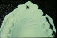 |
| Figure 135. Lower left canines and premolars erupted. Deep overbite being treated with utility arch. | Figure 136. Occlusal view of maxillary model showing anterior diastema. |
 |
 |
| Figure 137. Closing midline diastema using a combination of a limited banded technique and a labial elastic attached to an acrylic and wire appliance. | Figure 138. Occlusion after treatment. |
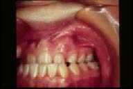
A continuous and controversial question in dentistry is what to do when a labial frenum is associated with a midline diastema.(29) Often, it is obvious that the frenum is present only because there is excess space and insufficient pressure of tooth eruption to cause resorption of the fibrous connection. There may be occasions, however, where the frenum attachment is so low and the tissue so fibrous that it may very well be the cause for the midline diastema. (Figure 142)
There is a rule in orthodontics that before a “frenectomy,” or the surgical removal of the frenum is attempted, every effort should be made to close the diastema orthodontically by the clinical methods previously described. There is usually an initial accumulation of the frenum tissue after space closure, followed by natural resorption. If the resorption does not take place after a certain length of time (usually three weeks) the frenectomy is then performed while retaining the orthodontic result. It is feared that if the frenectomy is performed prior to space closure, the scar tissue that forms as a result of the surgery will be more resistant than the original frenum. This will result in extreme difficulty during space-closing procedures.
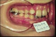
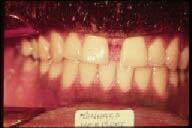
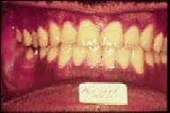
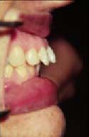
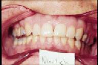
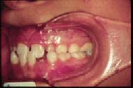
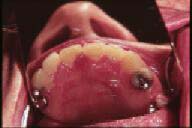
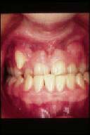
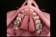
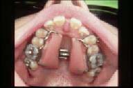
Figure 143 illustrates the profile view of protruding maxillary incisors, and figure 144 shows the frontal view of the occlusion. Note the midline diastema, the low frenum attachment, and the removable orthodontic appliance that was used to correct the malocclusion. The appliance consisted of an “active” labial Hawley wire to retract the incisors, and soldered hooks on the wire for potential use of elastic therapy. A view from the palatal side reveals mattress finger springs touching the mesial-palatal surfaces of the central incisors. (Figure 145) The combined activation of the labial Hawley wire, against the distal-labial surfaces of the central incisors, and the mattress springs on the mesial- palatal surfaces of these teeth correct their abnormal rotations, along with the anterior protrusion. Figure 146 illustrates the “angry” looking frenum as its fibers accumulated after the tooth movement procedures. Figure 147 shows the frontal view of the post-orthodontic frenum attachment. After sufficient time was given for the frenum to resorb naturally, it was surgically removed during the retention phase of orthodontic therapy. (Figure 148) Figure 149 illustrates the case after orthodontic treatment and the frenectomy procedure.
Various techniques can be utilized to perform a frenectomy on an abnormal labial frenum attachment following space closure of an anterior diastema. The latest method is the utilization of an electrosurgical technique. (Figure 150) This procedure is relatively efficient and causes the least amount of bleeding, since it cauterizes the capillaries during the surgical removal of the tissue. This technique also seems to cause less scar tissue than the traditional surgical approach using scalpels.
 |
 |
| Figure 139. Midline diastema. Note parallelism of central incisor teeth. | Figure 140. Plastic edgewise brackets are bonded on incisors with 0.016" round sectional arch wire. A 3/4 inch elastic was stretched across appliance to produce necessary force. |
 |
 |
| Figure 141. Occlusion after about four months of treatment. | Figure 142. Excessive diastema associated with an abnormal frenum attachment. |
 |
 |
| Figure 143. Protruding maxillary incisors. | Figure 144. Hawley appliance used to treat protruding incisors and to close diastema. |
 |
 |
| Figure 145. Palatal view of appliance showing mattress springs used to rotate central incisors. | Figure 146. Palatal view of hypertrophied frenum attachment after anterior space closure. |
 |
 |
| Figure 147. Hypertrophy of labial frenum following closure of midline diastema. | Figure 148. Frenectomy following space closure. |
 |
 |
| Figure 149. Occlusion after orthodontic treatment and frenectomy procedure. | Figure 150. Postsurgical view of frenectomy using electro-surgical procedure. Note all fibers of the frenum were removed, including those embedded in the upper lip. |
 |
 |
| Figure 151. “Pseudo” Class III malocclusion caused by anterior displacement of the mandible. | Figure 152. Palatal view of appliance to tip incisors forward. |
 |
 |
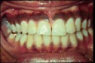
| Figure 153. Maxillary central incisors in correct position after orthodontic treatment. | Figure 154. The mandible has returned to its correct position after advancing the upper central incisors. |
 |
 |
| Figure 155. Maxillary left canine in palatal-version, causing an individual anterior cross bite. | Figure 156. Acrylic guide plane cemented to mandibular arch. |
The midface complex and the maxilla grow downward and forward at an earlier age in a child than does the lower face or mandible.(20) Therefore, it is not uncommon to observe a convex or “Class II” appearance in the face of a growing child before the mandible “catches up.” An anterior displacement of the mandible, due to local factors creating an anterior cross bite or a “pseudo” Class III malocclusion, may develop into a “true” skeletal Class III when the mandible begins to grow and develop normally.
An example of an anterior displacement of the mandible is shown in Figure 151. This anterior cross bite, due to the lingual inclinations of the permanent maxillary central incisors in the mixed dentition, may very well “lock” the maxilla and prevent its normal downward and forward growth. It is obvious that this problem should be treated early to also prevent any future temporomandibular joint dysfunction. Figure 152 illustrates the palatal view of the appliance used in the treatment of this case, showing a double helical loop spring palatal to the central incisors to produce labial movement of these teeth when activated. The posterior bite splint “dis-occludes” the anterior teeth and allows the upper incisors to move out of cross bite after the finger spring is activated. It is important to remember that the posterior bite splint acts in a manner opposite to an anterior biteplate. In other words, because the incisors are out of occlusion, they will have a tendency to “supra-erupt,” thereby deepening the anterior overbite.
Figures 153 and 154 show the case after approximately eight weeks of treatment. Note also the space regained for the maxillary right permanent canine. Retention of simple cross bite treatment, whether anterior or posterior, is usually not a problem, since the occlusion helps to maintain the corrected relationship. Even though this patient may require further orthodontic treatment in the future, it is evident that a more severe problem was prevented.
Occasionally, due to ectopic eruption, a misplaced tooth bud, an arch length discrepancy, or some other factor causing an individual malposition, an anterior tooth may be found in “palatal-version” and therefore in an anterior cross bite. (Figure 155)
These problems are often amenable to removable orthodontic appliance therapy, acrylic guide-plane treatment, limited fixed appliance mechanics, or a combination of these methods. One of the “older,” but very effective techniques used to treat individual anterior cross bites is the utilization of an acrylic guide-plane. After fabrication of the acrylic guide-plane, it is temporarily cemented to the lower dental arch, opposite to the malposed tooth. (Figure 156) The patient must be cooperative, and warned that it may cause some degree of trauma during mastication. Fortunately, the treatment time is relatively short with this appliance, and no damage is caused to the teeth during orthodontic therapy. To facilitate the treatment in this case, a fixed segmental arch wire with vertical loops was used to help in the labial movement of the maxillary left canine. (Figure 157)
Individual anterior cross bites can also be treated by the use of removable orthodontic appliances. Figures 158 through 160 illustrate a case utilizing a removable appliance with one mattress spring to advance the maxillary right central incisor. As mentioned previously, retention is seldom a problem after the treatment of individual cross bites, since the forces of occlusion aid in maintaining the tooth in its corrected position.
 |
 |
| Figure 157. Sectional arch wire with vertical loops attached to lateral incisor, canine and first premolar teeth. Segment of the wire attached to the canine is activated in a labial direction prior to ligation to the brackets. | Figure 158. Anterior cross bite in right central incisor region. |
 |
 |
| Figure 159. Acrylic and wire appliance with mattress spring to move right central incisor into a labial position. | Figure 160. After six weeks of treatment, anterior cross bite is corrected. |
The reason for a majority of posterior cross bites is usually skeletal rather than dental in origin. Often the maxilla is narrow when compared to the mandible, causing a discrepancy between the two jaws. The diagnosis of such skeletal dysplasias is best accomplished utilizing a frontal cephalometric radiographic analysis to determine the width discrepancies of the jaw structures.
The clinician must keep in mind that the maxilla actually consists of two separate bony structures, both growing in a transverse direction during the active growth of a child.(20) Because of its intimate relationship to the cranial base, it is thought that the growth in maxillary width follows the neural growth curve, which is complete quite early in life, perhaps as early as 7 years of age.(30) This does not mean, however, that the mid-palatine suture of the maxilla is fused at this early age. This suture does not fuse until the 20th year of life, but it is incumbent upon the clinician to use palatal widening procedures while the patient is actively growing, and prior to the fusion of the two halves of the maxilla. In so doing, the patient’s treatment is relatively uncomplicated, and the result is more stable.
Examples of skeletal cross bites can be seen in the deciduous, mixed, and permanent dentitions. The etiology of a narrow maxillary complex can be associated with a prolonged thumb sucking habit.(20)
As it was explained in a previous chapter, the “quad helix” appliance has been shown to produce orthopedic effects on the maxilla in the mixed dentition and during active craniofacial growth.(23) (Figure 161) In the adult patient, the midpalatine suture is “closed” and does not allow the forces produced by the quad helix appliance to separate the two halves of the maxillary bones. Therefore, in the adult dentition, the magnitude of force created by the activation of the quad helix appliance is in the tooth movement range and acts to expand the dental units in a collapsed arch. It can be said that the quad helix appliance is “age dependent,” creating orthopedic results on growing children, and tooth movement on adult patients.
The initial activation of the quad helix appliance is placed prior to cementation. An initial expansion of 8 mm will produce approximately 14 ounces of force. This magnitude is sufficient to produce tooth movement, but generally is not enough to create an orthopedic effect on adults when the midpalatine suture is closed. However, in children in the deciduous or early mixed dentition stages of development, the resistance at the patent suture is often less than in the dentoalveolar area. Therefore, this appliance is capable of orthopedically widening the maxilla in children and thereby creating a normal maxillo-mandibular relationship.
Once the appliance is cemented on the teeth, it is possible to make intra-oral adjustments to vary the forces on the dental segments. Such activations can be easily performed with a three-pronged pliers. The first adjustment is made at the anterior bridge, (Figure 162) and the second and third bends are made at the posterior one-third of the palatal bridges. (Figure 163)
There has been an evolution of removable and fixed appliances to expand collapsed dental arches or narrow maxillae. One of the first appliances designed for the “rapid” expansion of the palate was by Haas(31) after his experimentation on the maxillae of pigs. Interestingly enough, Haas found that more than any other experimental animal, the pig’s maxillary suture resembles the human’s structure. Since it is difficult to produce maxillary orthopedic effects after active growth has ceased, it has been found that rapid palatal expansion can be accomplished using the Haas appliance. Since these orthopedic appliances affect numerous sutures of the craniofacial complex, extreme care must be taken when using such devices. It is also extremely important for the clinician to perform a thorough pretreatment evaluation, especially using a frontal cephalometric analysis.(32) (Figure 164)
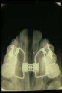
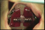
Figures 165 and 166 represent a skeletal cross bite in a 16 year old female patient. Although this patient may seem relatively young to most clinicians, she can be considered an adult in terms of the growth of her craniofacial complex, keeping in mind that the majority of growth of female patients is complete by the age of 13 years.(20) Figure 167 illustrates a palatal view of the appliance used to expand this case. The typical rapid maxillary expansion appliance is cemented to the maxillary first premolars and first permanent molars, augmented by a palatal jack-screw and acrylic extensions. The rapid maxillary expansion appliance is activated by slowly turning the threads of the jack-screw a full revolution at the time of cementation. The patient is then instructed to activate the appliance two one-quarter turns per day for about one week. The patient should be seen frequently during this important phase of treatment. Figure 168 reveals the amount of palatal expansion that had occurred after approximately one week of activation of the appliance. Figure 169 shows the palatal radiograph of the patient, revealing the mid-palatal suture opening. The opening in the suture is initially filled with connective tissue, after which time bony apposition occurs. Figure 170 illustrates the same radiographic view several months after palate separation. Note that the mid-palatal suture has filled with bone, and that the inter-dental fibers between the maxillary central incisors have brought the teeth together, closing the diastema that was created by the rapid palatal expansion. After sufficient expansion has been accomplished, the jack-screw is covered with acrylic and the appliance is kept in place for at least 90 days for proper retention and healing of the various sutures. (Figure 171)
 |
 |
| Figure 161. Quad helix appliance constructed on the model of a patient with mixed dentition and a narrow maxilla. | Figure 162. First intra-oral adjustment is made at the anterior bridge with a three-pronged pliers as shown here. |
 |
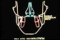 |
| Figure 163. Activation of the appliance with this adjustment expands and rotates the molars in the direction of the arrows. | Figure 164. Diagram of a frontal cephalometric radiograph to determine the need for palatal expansion. |
 |
 |
| Figure 165. A skeletal anterior and posterior cross bite in the adult dentition necessitating rapid palatal expansion. | Figure 166. Note Class III relationship and severe anterior cross bite. |
Clinicians who have never utilized rapid maxillary expansion appliances often ask what the patient’s symptoms or feelings are during the activation of the appliance. The author has found that the symptoms are relatively mild, other than a pressure sensation at the bridge of the nose during the initial activation. This is more than likely due to the effect of the suture between the maxilla and nasal bone. The clinician must keep in mind that these orthopedic appliances are actually medical devices. Used cautiously, they can produce meaningful results, but if abused, they could cause great harm to the patient. According to Gray(33), the maxillae articulate with nine bones, two cranial and seven facial. The activation of the rapid maxillary expansion appliances affects every one of these bones!(34)
Occasionally, one or more posterior teeth may be in unilateral cross bite. This cross bite usually arises from insufficient space for a tooth or several teeth to erupt properly into the dental arches. Most importantly, care must be taken that the cross bite is truly unilateral and not caused by a lateral displacement of the mandible. If the cross bite is reciprocal, due to displacement of the upper and the lower teeth, then inter-maxillary cross bite elastics can be used to treat both malpositioned teeth. (Figure 172) In most cases, a 1/4 inch - 3 1/2 ounce elastic is the one of choice for such treatment. The patient changes the elastic at least every other day in order to avoid using elastics that have fatigued, thus losing their potential to move the teeth effectively.(26)
Although the bucco-lingual vector of force is the one that the clinician is most concerned with in the treatment of posterior crossbites, it is the vertical pull that may cause damage to the teeth and the occlusion.(35) Not only can an excessive amount of force devitalize a healthy tooth, but it will also extrude the teeth, especially if the patient wears the elastics during mastication. This is especially important if the patient has an anterior open bite, since extrusion of posterior teeth will increase the severity of the malocclusion.
 |
 |
| Figure 167. Palatal view of a rapid maxillary expansion appliance prior to activation. | Figure 168. Palatal view of patient after one week of treatment with the rapid maxillary expansion appliance. |
 |
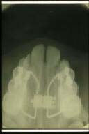 |
| Figure 169. Palatal radiograph of rapid palatal expansion after one week of treatment. | Figure 170. Palatal radiograph of rapid palatal expansion three months after the start of treatment. |
 |
 |
| Figure 171. Palatal jack-screw is covered with acrylic after treatment to retain the expansion for at least 90 days. | Figure 172. Intermaxillary elastic on palatal surface of upper tooth and buccal surface of lower tooth to reciprocally treat an individual cross bite. |
There are two types of forces used in orthodontics: orthodontic or tooth-moving forces, and orthopedic forces that affect the deeper craniofacial structures.(21) Orthodontic forces are those that are applied to the teeth by the wires of removable and fixed appliances. The force produced by the adjustments to these wires ranges from 50 to 500 grams, whereas orthopedic forces are much greater.
| Head Gear cervical high pull combination | (The head gear utilizes the upper molar tooth as a “handle” and transmits the forces to various sutures to treat Class II problems. Depending on the needs of the case, different vectors of force are used.) |
| Chin Cup Class III high pull | (The chin cup is used to transmit the forces to the developing mandible to treat Class IIIs or open bites.) |
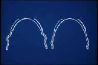
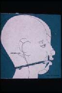
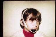
The head gear consists of an inner bow (Figure 173) that attaches to maxillary molars, and the outer bow which is connected to the inner bow. (Figure 174) Attached to the outerbow is an elastic mechanism around the patient’s head or neck. (Figure 175) The inner bow is made from 0.040" stainless steel round wire, and fits into the head gear tubes of the upper first permanent molar bands. In order to stop the inner bow in front of the molar tube, either a vertical loop or a “bayonet” bend is placed, as shown in Figure 173.
The outer bow is made of a stainless steel round wire of 0.050" in diameter. It is soldered in front to the inner bow with its ends bent in the shape of hooks for the connection of the rubber band or the elastic strap portion of the gear.
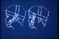
The most widely used orthopedic appliance to direct forces on the maxillary complex is the cervical gear or the Kloehn head gear, named after the person who invented it.(36) This is the type of device illustrated in Figure 175. The outer bow is connected to an elastic strap which is anchored around and behind the patient’s neck. Since the cervical position is lower than the maxillary molar teeth, this appliance has the tendency to produce an extrusive force on the attached teeth. This occurs, even though a patient is usually instructed to wear the appliance for a period of 12-14 hours per day, including the hours during sleep. Therefore, the cervical gear is contraindicated in an open bite type of malocclusion, since molar extrusion would complicate this type of problem.
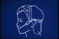
In order to avoid this complication, a “high pull” head gear is used, which produces a more superiorly directed vector of force. (Figure 176) This type of an appliance prevents the extrusion of the upper molars, but its efficacy in causing distal movement is relatively slight. A combination head gear can be used which takes advantage of the distal pull of the cervical gear and the high pull of the head gear. (Figure 177)
 |
 |
| Figure 173. Inner bow of head gear, with vertical loops (left) and bayonet bends (right) to stop the inner bow in front of the molar tubes. | Figure 174. Inner bow connected to the outer bow to complete the head gear assembly. Hooks of the outer bow are for attachment of elastics. |
 |
 |
| Figure 175. Diagram of Kloehn neck gear. Vectors of force are directed below the plane of occlusion causing extrusion of upper posterior teeth. | Figure 176. High pull head gear. Superiorly directed vectors of force prevent extrusion of posterior teeth. |
 |
 |
| Figure 177. Diagram of combination head gear with high pull and cervical vectors of force. | Figure 178. Dr. Angle’s original combination head gear. |
 |
 |
| Figure 179. Chin cup appliance to redirect the growth of the mandible and treat a skeletal Class III malocclusion. | Figure 180. Diagram of chin cup appliance for treatment of skeletal Class III (left) and skeletal open bite (right). |
 |
|
| Figure 181. Dr. Angle’s original “head cap” appliance. |
Although they were “re-popularized” by Kloehn in the 1950’s, orthopedic appliances are certainly not what one would call new. In the late 1800’s, Angle, the “father” of modern orthodontics wrote about orthopedic forces and how they could effect the maxilla and mandible.(37) Figure 178 reveals Angle’s first head gear, in this case a combination gear utilizing both cervical and high pull vectors of force.
Just as head gears apply orthopedic forces to the upper jaw to redirect the growth of the maxilla in Class II skeletal malocclusions, the chin cup appliance places orthopedic forces on the mandible to redirect the growth of the lower jaw during the treatment of Class III skeletal malocclusions. (Figure 179) Figure 180 illustrates the chin cup for treatment of Class III malocclusions on the left, and on the right, a high pull chin cup showing the vertical vector of force during the treatment of skeletal open bite malocclusions.
Long before their current use, Angle explained the utilization of chin cups to produce orthopedic forces on the mandible in the treatment of skeletal Class III malocclusions.(37) He termed this device a “head cap.” (Figure 181)