| Contents | Previous | Next |
Control of tooth movements is enhanced when appliances are fixed to the teeth. While removable orthodontic appliances can only tip teeth, fixed appliances can produce any type of tooth movement. By applying certain controlled forces to the tooth crown via the fixed appliance, apical and bodily movements, as well as rotations can be obtained. Controlled intrusion and extrusion of teeth are also possible.
As mentioned in the previous chapter, one of the reasons for the exclusive use of fixed orthodontic appliances by specialists in the United States is the strong educational influence that the “father” of modern orthodontics, Dr. Edward Angle, had not only on past clinicians but even the contemporary orthodontists.(1)(2) Dr. Angle’s biggest contribution to fixed orthodontic appliance development was his advent of the “edgewise” appliance. “Edgewise” refers to the fact that a rectangular wire is placed into a rectangular bracket on the tooth with its longest dimension being horizontal, or in a facial-lingual/palatal direction. This will become more evident when the various edgewise brackets are illustrated later in this chapter. The alignment of the rectangular wire in the rectangular slot of the bracket allows for proper tooth positioning, and especially expansion of the dental arches. It must be remembered that Dr. Angle was vehemently against the extraction of teeth for orthodontic purposes, and relied solely on the expansion of the dental arches to treat any crowding that existed. It was found later, when clinicians saw the need to extract teeth during arch length-tooth mass discrepancy cases, that the heavy edgewise appliance was not very capable of closing extraction spaces efficiently.
In the 1930’s, Dr. Joseph Johnson developed his “twin-wire” appliance, utilizing two light wires placed in the same bracket, thinking that two light wires would place more of a physiologic force on a tooth than would one heavy wire.(11) Because of the difficulty in achieving the proper tooth angulation during extraction cases, this appliance has more or less dropped out of favor by the contemporary clinician.
As fixed orthodontic appliance techniques evolved, other clinicians such as Begg(12), Jarabak(13), Tweed(14) and Ricketts(15) developed their own mechanisms to control tooth movement to their liking. It is not the scope of this text to try and explain each and every one of the fixed appliance techniques that are available to the clinician. It is only with the hope that the reader understands the basic advantages of fixed orthodontic appliances in the treatment of certain malocclusions. It must be remembered that a thorough understanding of diagnosis and treatment planning is more important than the appliance itself, since the latter is often a matter of personal preference and dictated by the educational background of the clinician.
Just as there are certain instruments important for the construction of removable orthodontic appliances, there is an armamentarium of instruments with which the clinician should be familiar regarding the manipulation of fixed orthodontic appliances as well.
The Bird Beak and Three Pronged Pliers have already been discussed in the previous chapter with respect to their use for removable orthodontic appliances. These are also important pliers for the bending of wires for most fixed orthodontic appliances.
The Pin Cutter and the Hard Wire Cutter have also been illustrated for you in the previous chapter. It must be remembered that because the pin cutter is a delicate instrument, it should only be used for cutting fine wires such as ligature wires. The hard wire cutter is used for cutting all other wires, and should never be utilized intraorally.
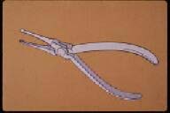
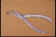
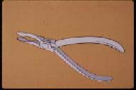
These are often referred to as “utility pliers,” as their purpose is mostly to place and remove arch wires to and from the mouth rather then the actual bending of wires as was discussed with the bird beak and three-pronged pliers. As is the case with the wire bending pliers, it is important for the clinician to understand the correct use of the wire-holding pliers as well. The reader should also keep in mind that one wire-holding pliers may be substituted for another, as the use of these pliers is often a matter of personal preference and the educational background of the clinician.
|
|
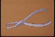
| Figure 54. Straight Howe pliers. | Figure 55. Howe curved pliers. |
|
|
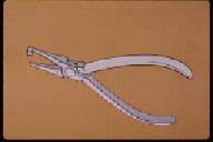
| Figure 56. Weingardt utility pliers. |
 |
 |
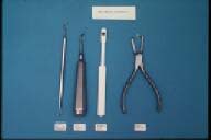
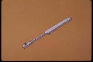
| Figure 57. Instruments used for orthodontic banding procedures. | Figure 58. Band pusher. |
 |
 |
| Figure 59. Band biter. | Figure 60. Band contouring pliers. |
 |
|
| Figure 61. Band removing pliers; blunt end (top), sharp beak (bottom). |
The principal components of fixed orthodontic appliances are:
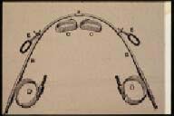
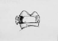
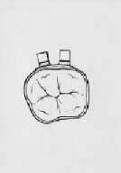
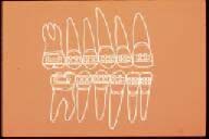
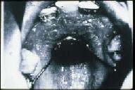
Orthodontics bands have a long historical evolution. Angle’s original fixed orthodontic appliance consisted of bands that were made of strips of a gold alloy, formed to the tooth, “pinched,” soldered, and cemented to the appropriate tooth.(3) (Figure 62) From this early period, the band material developed into strips of stainless steel, again formed to the tooth, “pinched,” welded and cemented to the tooth. In the 1960’s, preformed bands became widely utilized and simplified the actual orthodontic banding procedures. Direct bonding of brackets to the tooth structure was developed in the early 1970’s, and many thought this would be the end to the orthodontic band.(16) However, banding is still the method of choice, especially in the posterior region of the dental arches.
A tight-fitting orthodontic band serves several purposes during the treatment of a malocclusion. First, it protects the tooth from caries. This has become more evident with the advent of bonded brackets. Because the tooth is not covered on the interproximal surfaces, more caries are found during and after orthodontic therapy with the bonded system than with treatment that is performed with well-fitted orthodontic bands. Second, an orthodontic band is utilized to place the various attachments for the application of orthodontic, and sometimes orthopedic forces. The traditional method of fixing attachments is by welding them to preformed stainless steel bands which are then cemented to the teeth with zinc-oxyphosphate or a similar cement. The cement not only helps to hold the band in place, but also prevents the formation of plaque between the band and the enamel of the tooth. The integrity of the cement should be checked at every visit because if it leaches out, serious enamel demineralization can occur rapidly. As mentioned previously, a well-formed and tight-fitting band affords a certain amount of “self retention.” In other words, the clinician should not only rely on the adhesive capabilities of the cement to hold the band in place.
Band Placement
Several manufacturers supply preformed, pre-welded orthodontic bands. Generally speaking, each company’s bands have different techniques for the correct placements. The following procedure is the “average” technique used in the placement of most of the bands on the market today.
Anything welded or soldered to an orthodontic band is termed an “attachment.” These are the most important parts of the band and serve to attach the arch wires and various devices for force application. The two most common attachments are the brackets and tubes of the fixed appliance and are used for the insertion of the labial arch wires.
The type of attachments utilized in fixed orthodontic therapy depends on the type of appliance and treatment philosophy of the clinician. As mentioned previously, Dr. Edward Angle, the “father of modern orthodontics”, is the person that should receive the credit for the development of the appliances used today.(1) The single most popular contemporary fixed orthodontic appliance is the “edgewise” appliance, which was developed by Dr. Angle in the 1920’s.(3) The following attachments are those used in this type of mechanotherapy.
Brackets
 |
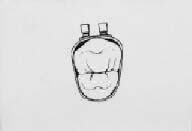 |
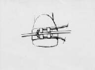
| Figure 62. Dr. Angle’s original fixed appliance, with strips of a gold alloy material “pinched” and soldered together to form orthodontic bands. | Figure 63. First the band should be fitted to the correct size. |
 |
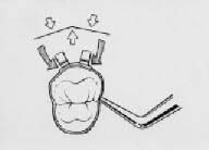 |
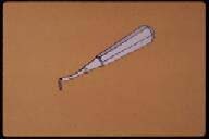
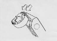
| Figure 64. Crimping of the band using three-pronged pliers. | Figure 65. Adapting the band to conform to the tooth using an amalgum plugger. |
 |
 |
| Figure 66. The occlusal edge of posterior bands should be placed at the mesial and distal marginal ridges of the teeth. The attachment should be at the middle one-third of the tooth’s facial surface. | Figure 67. From an occlusal view, the bracket should be placed at the center of the mesiodistal dimension of the tooth. |
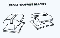
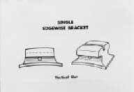
Single edgewise bracket (Figure 68). The two sizes of slots used in the edgewise technique are 0.018" X 0.025" and 0.022" X 0.028". The first dimension is the gingival-occlusal/incisal measurement, and the second is the facial-lingual/palatal distance. The rectangular slot receives a rectangular wire in an “edgewise” fashion, hence the name of the bracket and technique.
The gingival-occlusal/incisal measurement is the most critical of the two, since this distance limits the size of the archwire that can be placed into the slot. Obviously, those clinicians who favor a “light wire” technique will select the 0.018" X 0.025" bracket, and those dentists who tend toward using heavier forces during orthodontic therapy will choose the 0.022" X 0.028" bracket. It is the author’s opinion that one-half of the orthodontists today use the smaller bracket, and the other one-half tend toward utilizing the larger bracket. In fact, it is common to refer to one as using the “018” system, and the other clinician as using “022” mechanics. In capable hands, it does not matter which bracket is used, as long as the clinician uses appropriate mechanics that follow correct biological force systems.(10)
One disadvantage of a single bracket in the middle one third of the tooth, mesio-distally, is that it does not enable the clinician to correct for tooth rotation very efficiently. This led to the development of another type of edgewise bracket which will be explained later in this chapter.
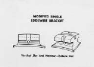
Single edgewise bracket with vertical slot (Figure 69). This variation of the edgewise bracket is used when the technique calls for the placement of auxiliary springs through the vertical slot lingual or palatal to the bracket slot. Such springs can be used to upright and tip teeth in various directions. This is a common bracket utilized by Dr. Broussard in his technique which uses various vertical auxiliaries to retract and upright teeth for closing mechanics after the extraction of premolars.(17)
Single edgewise bracket with vertical slot and narrow ligature slot (Figure 70). This variation of the vertical slot bracket also has a ligature slot in case the clinician desires to tie the arch wire to the mesial or distal portion of the bracket. This technique would help to achieve rotation of a tooth, which is an advantage over the single edgewise bracket previously described.
Single edgewise bracket with vertical slot and wide ligature slot (Figure 71). This variation of the previous bracket has a wider ligature slot to facilitate the mesial or distal rotation of a tooth. In order to rotate the tooth mesially or distally, the clinician would tie the arch wire only to the ligature slot on the side of the tooth that is rotated toward the lingual or palatal side of the dental arch in order to pull that side of the tooth toward the facial surface.
 |
 |
| Figure 68. Single edgewise bracket. | Figure 69. Single edgewise bracket with vertical slot. |
 |
|
| Figure 70. Single edgewise bracket with vertical slot and narrow ligature slot. |
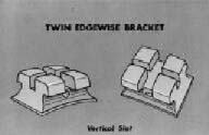
Twin edgewise bracket with vertical slot (Figure 72). The previous bracket led to the development of the “twin bracket” which is the most common one used today by orthodontic specialists. This bracket is a variation of the single bracket as well as the one with ligature slots. Instead of a ligature slot, there are two distinct bracket “wings” for easier rotation adjustments. Depending on the type of rotation, the arch wire is tied to one or the other wing in order to properly rotate the tooth.
Bonding of Brackets
Traditionally, brackets were soldered or welded onto orthodontic bands, and the bands were then cemented to the teeth. The usual manner now is to bond the brackets, especially in the anterior segments of the dental arch, directly to the teeth with various acrylic bonding systems.
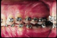
The first attempt of bonding brackets or other attachments to tooth structure was by the use of various types of copper cement as the adhesive. Although copper cements afforded more adhesion than typical zinc phosphate cements, most attempts to use this material for bonding purposes failed. It was in the early 1970’s that our colleagues from Japan developed a true bonding system for orthodontics that is almost universally used today to bond brackets to anterior teeth.(16) The reason why bonding should be limited to anterior teeth is because the forces of the posterior occlusion have a tendency to dislodge posteriorly bonded brackets. Preformed orthodontic bands with prewelded attachments are still the method of choice in the posterior segments of the dental arch. The author does not feel it is necessary to delve into a step-by-step bonding procedure for orthodontic puposes. The general dentist knows this system well, since the steps for bonding orthodontic brackets are similiar to the technique used to bond restoration materials to enamel. (Figures 73 and 74)
Tubes (Figure 75)
The other attachments soldered or welded on orthodontic bands are molar tubes, on the last molar banded, which is usually the first permanent molar. In certain circumstances, the second permanent molars are also banded. Then, these are the teeth whose bands receive the tubes, and all of the preceding teeth, including the first permanent molars have brackets soldered or welded to their bands. In other words, the most posterior teeth on which bands are placed receive the tubes, and all other teeth have brackets as attachments.
Maxillary Tubes
There are two or three tubes placed on the upper molar band. One is for the insertion of the head gear, and another one or two tubes for placement of the labial arch wire/s.
Head gear tube. This is a round tube, and the diameter is usually 0.045", the size of the inner bow of the head gear. It can either be placed gingival or occlusal to the arch wire tubes.
 |
 |
| Figure 71. Single edgewise bracket with vertical slot and wide ligature slot. | Figure 72. Twin edgewise bracket with vertical slot. |
 |
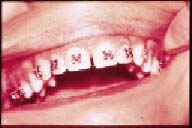 |
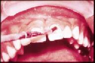
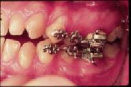
| Figure 73. Etching of enamel prior to bonding bracket. | Figure 74. Brackets bonded to upper anterior teeth.. |
 |
 |
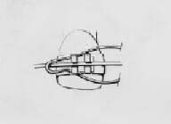
| Figure 75. Tubes attached to the last upper and lower molar bands are of similar size as the brackets. | Figure 76. Hooks soldered on molar bands used to attach elastics for inter-maxillary traction. |
Placing it gingival causes the molar to tip less than placing it toward the occlusal, when the forces of the head gear act on the tooth. On the other hand, placing the head gear tube toward the occlusal allows the patient an easier access for the placement of the headgear.
Arch wire tubes. Depending on the technique, there are either one or two arch wire tubes. These are rectangular, and are the same size as the brackets used in the edgewise appliance (0.018" X 0.025" or 0.022" X 0.028")
Mandibular Tubes
Arch wire tubes. As seen on the upper, there are either one or two arch wire tubes on the lower molar band as well. Again, the tubes are rectangular, and are the same size as the brackets used in the edgewise appliance.
Auxiliaries
Occasionally, there may be another attachment on the molar band. There may be a ball or hook on the facial surface of the band for the placement of intermaxillary elastics during the treatment of Class II or Class III malocclusions. (Figure 76) Also, a hook or ball may be soldered or welding onto the palatal surface of the upper molar band for the attachment of elastics during the treatment of posterior cross bites.
Requirements of Orthodontic Wires
From the outline above, one can see what the requirements are of an ideal wire material for orthodontic purposes. All orthodontic wires are made from an alloy, which is defined as “any combination of two or more metals.”
Historically, the types of wires that have been used for orthodontic purposes have been:
Gold alloy was the first material used in orthodontics. It was ideal as far as its ease of manipulation, and it could be “heat-treated” in order for it to maintain its shape and produce a controlled force delivery system. However, gold is very corrosive in the oral cavity, and its cost now makes this material prohibitive for use in orthodontic treatment.
Stainless steel alloy has been the material that has been traditionally used in modern orthodontics. It is relatively easy to manipulate, it is non-corrosive in the oral cavity, and it is capable of an effective controlled force delivery system.
Cobalt-chromium-nickel alloy wires have the same ideal characteristics of the gold alloy wires that were once popular in orthodontics. They are very malleable, they can be heat-treated to be capable of delivering effective forces, and they have the advantage over gold of not being corrosive in the oral cavity.
The nickel-titanium wire alloy can be considered a “space age” material. Its commercial name is “Nitinol” wire and derives its name from the first two letters of the words nickel and titanium, and “nol” standing for the Naval Observatory Laboratory where this alloy was first developed. “Ni-Ti” wires have the advantage of being very “springy.” In other words, they are capable of bending a large distance without becoming permanently deformed. These are ideal wires to use during the initial stages of orthodontic treatment when light round wires of this material are used for the initial stages of therapy.
Shapes of Orthodontic Wires
Round wires are most commonly used at the outset of orthodontic treatment for such things as “leveling” the arch and tooth rotation.(Figure 77) As mentioned in the previous chapter, the size of these wires is designated by the diameter of the wire in inches. Usually, smaller wires are used first, followed by larger wires, depending on the tooth movement desired and the size of the brackets and tubes used in the appliance. The sizes of round orthodontic wires used in fixed appliance therapy range from 0.014" to 0.022". The size of the brackets and tubes that the clinician utilizes will determine the largest wire that can be used during treatment. The inner bow of the head gear is also a round wire, and its size is usually 0.045". Lingual arches, such as those used for space maintainers or retainers, are made from round wires, the size usually being 0.040.”(Figure 78)
Rectangular wires are used after round wires during the treatment of a typical malocclusion. (Figure 79) The wires fit into the rectangular brackets and tubes in an “edgewise” fashion, and allow the clinician to control the movement of the tooth in all planes of space. (Figures 80 and 81) The size of rectangular wires vary greatly, and are too numerous to discuss. A typical rectangular wire is 0.016" X 0.022,” the first measurement being the incisal/occlusal-gingival dimension, and the second being the facial- lingual/palatal dimension. There is a direct correlation between the size of the arch wires and the force transferred to the teeth.
Segmented or Sectional Wires
Aside from using a continuous wire on the facial side of the dental arches from one last permanent tooth to the other, a segmented or sectional wire can also be used in certain circumstances. (Figure 82) This is especially true in fixed orthodontic cases treated by a general practitioner when only a limited number of teeth need to be moved.
Ligature Wires
Once the band is placed and cemented properly to the tooth, the labial arch wire is ligated to the bracket using a “dead-soft” stainless steel wire of 0.009 to 0.011 inches in diameter. The purpose of the ligation is to secure the wire to the bracket so that the proper forces can act on the tooth. (Figures 83-85) Another method of securing the arch wire to the bracket is with elastic modules called “alastics.” (Figure 86) This is usually done during the final stages of treatment, or when significant forces are not required to move a tooth, because the rubber material of the elastic modules has a tendency to stretch and lose its effectiveness.
 |
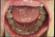 |
| Figure 77. Upper and lower round arch wires used for initial stages of treatment. | Figure 78. Lingual arch used for retention. |
 |
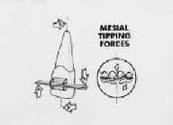 |
| Figure 79. Rectangular arch wires used for later stages of treatment. | Figure 80. A mesial tipping force (left) is placed on an upper left central incisor by torquing the wire in a clockwise direction. A straight wire produces the same movement on a malposed tooth (insert) as long as the bracket is positioned correctly on the tooth and the wire is not permanently deformed. |
 |
 |
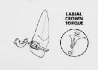
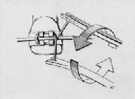
| Figure 81. A rectangular wire is adjusted in the direction of the arrow (left) in order to produce labial crown torque. Insert shows the direction of the tooth movement. As the crown is torqued in a labial direction, the root moves toward the palate. | Figure 82.Upper and lower segmented or sectional arch wires. |
 |
 |
| Figure 83. The looped ligature wire is placed so that the “lead” portion is outside the arch wire. | Figure 84. The incisal and gingival portion of the ligature wire are tucked under the corresponding parts of one bracket. |
 |
 |
| Figure 85. The tails of the ligature are brought together, and the tie is begun; in this case they are turned in a counter-clockwise direction. The tail is continued so enough wire is available to cut and tuck under the arch wire. | Figure 86. Elastic modules used to secure the arch wire to the brackets. |
 |
 |
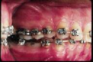
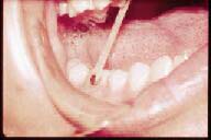
| Figure 87. Elastic therapy to treat a posterior cross bite. | Figure 88. Headgear to reinforce achorage of upper molars. |
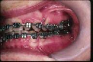
We learned in the previous chapter that removable orthodontic appliances require a certain amount of anchorage for proper retention. Anchorage for fixed appliance therapy is an entirely different concept. It means “the nature and degree of resistance to displacement offered by an anatomic unit when used for the purpose of tooth movement.” In simple terms, when a force is placed on a tooth, there is an “equal and opposite” force created. It is easy to understand when one thinks about a reciprocal force between two teeth, as is the case when a simple cross bite is treated using elastic therapy. (Figure 87) As in this example, a clinician would want these two teeth to move “reciprocally.” In other cases, the dentist may want to “reinforce” the anchorage value of a tooth that he or she would like to remain stationary. A lingual holding arch, described previously, is one example of reinforcing the mandibular molars when the clinician does not want them to move forward. In the maxilla, two methods of choice are the headgear (Figure 88) and the palatal holding arch (Figure 89) to hold the maxillary molars in place while retracting anterior teeth. An entire chapter could be devoted to this important topic, but the author believes that if the clinician understands the above description of anchorage, he or she should be able to use this philosophy to his or her advantage during limited fixed orthodontic therapy.
 |
|
| Figure 89. Nance palatal holding arch to reinforce anchorage. |