| Contents | Previous | Next |
Orthodontic specialists, especially those trained in the United States, have minimized the use of removable orthodontic appliances. This is mainly due to their postgraduate training in the exclusive use of fixed appliances, as well as the fact that “older” clinicians never had the opportunity to utilize removable appliances in their undergraduate orthodontic training, since this curriculum did not exist in the “old days.” Another reason for the exclusive use of fixed orthodontic appliances by specialists in this country is the strong educational influence that the “father of modern orthodontics,” Dr. Edward Angle, had not only on past clinicians but even the contemporary orthodontists(1),(2). His strict disciplinary approach and his dogmatic use of fixed appliances still ring in the minds of orthodontic specialists today. In fact, the edgewise fixed orthodontic appliance developed by Dr. Angle in 1928 is still being utilized today, with some variations(3). Also, orthodontic specialists have the feeling that removable appliances should be limited to retention after active orthodontic therapy. This notion could be traced to the early publication in 1919 by Dr. C. Hawley who wrote about his “Hawley retainer,” a removable appliance that is still popular and utilized today(4).
Clinicians in other countries, especially those from European nations, have always been very well versed in the utilization of removable orthodontic appliances(5). Some well known clinicians even pioneered the use of certain removable appliances to stimulate, or at least help to develop the growth of jaw structures(6),(7). These dentists have known how to utilize removable appliance therapy, and most importantly, the appliances’ limitations.
There is an axiom that has dwelled in the mind of the author, learned early from a progressive orthodontic educator, Dr. T. M. Graber, who has even advocated the use of removable bite plate appliances to aid in the treatment of certain temporomandibular joint disorders (8). The axiom is: “The tooth does not know what appliance is being used.” In other words, if the clinician thoroughly understands the diagnosis of a particular case, he or she should be able to use the appropriate orthodontic appliance, whether removable or fixed, to “get the job done.” Because of Dr. Graber’s influence, along with study and clinical experience, the author has always advocated the use of proper removable appliance therapy(9). As we have learned from our European colleagues, not all cases can or should be treated by the use of removable appliances. Hopefully, the writings in this book will aid the dentist in the proper use of removable orthodontic appliances, as well as their limitations.
A removable orthodontic appliance is one which is easily removed for cleaning, but which is firmly attached to the supporting structures so that controlled pressure is brought to bear on the teeth to be moved. The design and construction of any removable orthodontic appliance must begin with a detailed plan of the tooth movement that is to be carried out in the course of the treatment of a particular case. If the treatment is at all complicated, it is important to consider how many movements can be carried out with one appliance alone or, if necessary, to break down the treatment plan to a series of simple tooth movements, using a separate appliance for each.
|
|
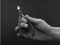
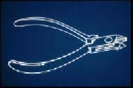
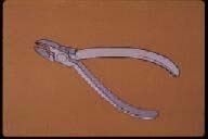
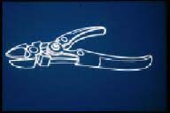
| Figure 1. Bird beak or #139 pliers. | Figure 2. Pyramidal beak (left) and cone-shaped beak (right). |
|
|
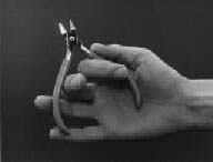
| Figure 3. Finger and pliers placement for bending wire. | Figure 4. Three-pronged pliers. |
|
|
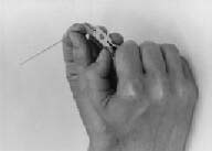
| Figure 5. Pin- or ligature-cutting pliers. | Figure 6. Hard wire cutter. |
Proper instrumentation is as important in orthodontics as it is in other clinical dentistry procedures. Whether sharpening the line angles of a cavity preparation or placing an important bend in an arch wire, the clinician must properly manipulate various instruments. The average dentist, however, is relatively unfamiliar with orthodontic instrumentation because of the limited experience afforded in most dental school curricula. Therefore, an attempt will be made to illustrate and explain the use of the basic pliers and orthodontic instruments necessary for the construction of removable orthodontic appliances.
A more detailed explanation of the types of wires used in orthodontic clinical practice will be given later in the text when fixed appliance therapy is discussed. The basic wires used for removable orthodontic treatment are made from a stainless steel material and are almost always round in shape. Therefore, the following is a discussion of the various wire sizes used in the construction of removable orthodontic appliances.
Along with the proper instrumentation, the clinician should be aware of the various wire sizes used in the construction of most removable orthodontic appliances. As mentioned previously, round stainless steel wires are usually used for these types of appliances. Although the metric system is used in most countries other than the United States, the size of a round wire utilized for orthodontic purposes is universally designated by the diameter of the wire in inches.
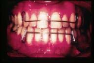
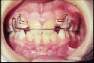
The most common removable appliances used for “active” orthodontic tooth movement are the acrylic and wire appliances. “Active” treatment is differentiated from “passive” treatment, the former being defined as the actual treatment of a particular case, and the latter meaning the retentive part of the therapy. Retainers can also be acrylic and wire appliances, but in most cases, they do not contain the “active elements” of an appliance, which are the various finger springs that cause tooth movement when activated.
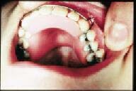
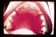
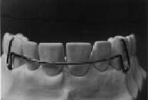
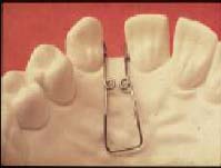
The design of a removable appliance will be considered to be composed of three parts. (Figure 7): 1) the acrylic baseplate that covers the palate of the maxilla or the lingual tissue of the mandible, 2) the retentive clasps around the premolar and molar teeth, and 3) the active elements.
The greatest portion of a removable orthodontic appliance is the baseplate. It is usually made of acrylic and has three main purposes: 1) Acts as a vehicle and carries all working parts and active elements such as clasps and finger springs. 2) Serves as anchorage or retention. It must be remembered that similar to removable prosthetic appliances, removable orthodontic appliances are primarily “tissue-bearing” appliances, and close adaptation is essential for proper retention of the appliance. 3) Acts as an active element of the appliance.
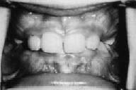
With regard to the baseplate being a part of the active element of the appliance, an anterior bite plate is often built into the baseplate. (Figure 9) The lower incisors occlude on the acrylic behind the upper anterior teeth, the posteriors are out of occlusion, and this allows the latter teeth to erupt and concomitantly open the bite in deep overbite cases. (Figure 10) The clinician, however, should understand the basic fundamentals of clinical cephalometrics with respect to the patient’s facial type and vertical dimension before he or she attempts to open a patient’s bite in this manner.(10)
The baseplate may also be utilized to expand the maxillary dental arch. (Figure 11). Differential diagnosis is important in order for the clinician to determine whether the constriction is due to a collapsed dental arch, or due to insufficient maxillary growth. The difference between orthodontic and orthopedic forces must be understood as well as the importance of the extra-oral muscle forces.(10)
 |
 |
| Figure 7. Acrylic and wire appliance - acrylic baseplate, retentive clasps, and active element. | Figure 8. Acrylic baseplate of removable appliance. |
 |
 |
| Figure 9. Anterior bite plate. | Figure 10. Deep overbite (vertical incisor overlap). |
 |
 |
| Figure 11. Maxillary expansion appliance. | Figure 12. Maxillary baseplate covers entire palate. |
For every action, there is an equal and opposite reaction. Every spring pressing against the tooth develops force in the same quantity against the baseplate of a removable orthodontic appliance. After the directions of the tooth movement are carefully analyzed, it is necessary to assess the reaction which will be produced and to make plans for suitable teeth to resist it.
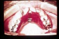
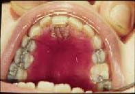
In the maxillary removable orthodontic appliance, it is usually better to cover the entire palate at least to the distal side of the first molar. (Figure 12) This is accomplished for two reasons: 1) This type of design is intrinsically stronger and provides more anchorage than the so-called “horseshoe” appliance which only partially covers the palate; 2) The tongue is less likely to catch and dislodge the appliance under a complete acrylic palate. Many clinicians mistakenly feel that covering the entire palate will elicit a “gag” response from the patient. However, it must be remembered that the patient’s gag reflex is on the base of the tongue and not on the palate.
During this author’s early training, an astute clinician showed him the best method of taking an impression of a patient with an overly sensitive gag reflex. That is, to lean the patient back in a horizontal position so that the patient’s tongue drops down toward the throat. Then, seat the distal portion of the impression tray toward the back of the palate first, and allow any excess impression material to flow forward toward the incisor region as the tray is fully seated.
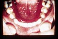
The lower baseplate presents special problems. (Figure 13) Because the lingual sulcus is shallow, it is necessary to make the lower baseplate shallow as well, and thus some extra thickness is often needed for strength. Also, there is usually a deep lingual undercut in the molar area, and it is then necessary to “ease” the baseplate in this region and to avoid these undercuts. Figure 14 illustrates how a clinician can construct a lower baseplate properly by “blocking out” the lingual undercuts prior to the construction of a mandibular removable appliance.
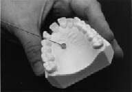
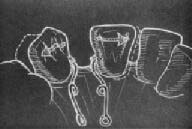
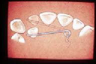
Although most of the retention capability of a removable appliance is accomplished by adequate tissue adaptation of the baseplate, most appliances require some form of wire retentive clasps to provide the stabilization needed. The type of clasp chosen for added retention of a removable orthodontic appliance depends on the undercuts or on the retention surfaces of the teeth to be clasped. (Figure 15) There are several types of retentive clasps that help distribute the active force through the baseplate into the soft tissue. As mentioned previously, 0.025" round stainless steel wires are used in the construction of retentive clasps.
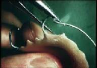
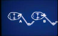
This is one of the most commonly used clasps for retention of removable orthodontic appliances. It should be especially designed to take advantage of the undercuts found mesially and distally on the buccal aspect of the permanent molars. Accordingly, when this type of molar clasp is used, a maximum length of wire should lie along the gingival area of the tooth in order to take full advantage of all the existing undercuts on the mesial, distal, and buccal surfaces of the tooth. (Figure 17)
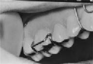
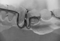
This is one of the most efficient clasps used for retentive purposes. This clasp brought to the removable appliance technique the great advantages of extreme security and reliability of retention on semi-erupted teeth, features which could not always be achieved with the circumferential clasp. There are several important points to remember about the arrowhead clasp: 1) The “arrowhead” should not touch the adjacent teeth. 2) The “bridge” of the clasp should lie approximately 2mm clear of the buccal or facial surface of the tooth. 3) The “arrowhead” should be in contact with the tooth only at the extreme ends. (Figure 19) There is nothing to be gained by making the bends excessively sharp, as this will only weaken the wire and increase the possibility of breakage.
A third and popular type of retentive clasp is named the “ball” clasp. It derives its name from the tiny ball at the end of the wire that crosses from the baseplate at the interproximal area of two posterior teeth. The ball is bent toward the interproximal surfaces of those two posterior teeth, taking advantage of the undercut surfaces in that area. Care must be used not to bend the ball too far in toward the gingiva as to not cause any tissue irritation.
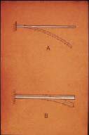
The action of a removable orthodontic appliance depends on the action of the auxiliary springs used. In planning the design of the auxiliary springs, it is important to design a spring that will exert suitable pressure over an adequate distance. Springs may be divided into three different types: the labial wire spring, the free-ended springs, and the accessory spring.
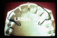
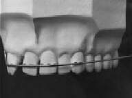
This spring is attached at both ends of the baseplate, as in the Hawley labial wire. This appliance is similar in design to the Hawley retainer appliance mentioned previously.(4) (Figure 22) As will be illustrated later in this text, the Hawley appliance can be an “active” appliance as well as a “passive” retainer, by certain activations of the labial wire. (Figure 23) The labial wire should be bent in progressive stages with extreme attention to accurately fit at each step to ensure a well-formed arch.(Figures 24-26) As mentioned previously, 0.032" stainless steel wire is used in the construction of labial wire springs.
The Hawley wire is probably the most common spring used in removable orthodontic appliance therapy. It can be utilized in both the maxillary and mandibular dental arches for palatal or lingual tipping of the incisor teeth. The indication for its use is generalized anterior spacing caused by excessive labial tipping of anterior teeth. The activation of the loops applies a lingual or palatal force on the labial surfaces of the anterior teeth, and the removal of the acrylic on the lingual or palatal aspect of the baseplate guides the teeth in a posterior direction. A lower Hawley appliance often is used to fulfill the objective of procedural movement which has been discussed in the literature.(10). Often, mandibular anterior teeth must be retracted first in order to make possible the palatal movement of the maxillary anterior teeth.
 |
 |
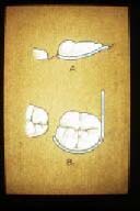
| Figure 13. Mandibular removable orthodontic appliance. | Figure 14. A) and B) the baseplate is made too short; C) the plate is made longer by blocking out undercuts. |
 |
 |
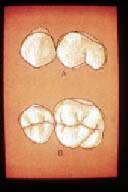
| Figure 15. A) buccal and B) occlusal views of undercut areas. | Figure 16. Circumferential clasp |
 |
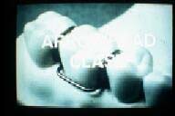 |
| Figure 17. A) buccal and B) occlusal views of clasp. | Figure 18. Adams or “arrowhead” clasp. |
 |
 |
| Figure 19. “Arrowheads” contacting mesial and distal undercuts. | Figure 20. Ball is bent at interproximal undercut areas. |
 |
 |
| Figure 21. Hawley labial wire. | Figure 22. Upper and lower “active” Hawley appliances. |
 |
 |
| Figure 23. Activation of Hawley loop. | Figure 24. Palatal portion of Hawley wire to be embedded into acrylic baseplate. |
Mattress Spring (Figure 27)
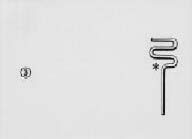
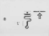
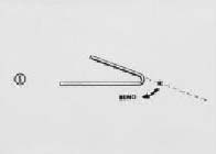
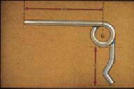
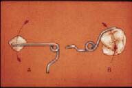
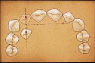
The mattress spring is an example of a free-ended spring. It is utilized for labial movement of teeth in crossbite, if the crossbite is not a symptom of a general malocclusion, if there is adequate space in the arch at the site of the crossbite, and if the tooth in question is sufficiently complete in its development. (Figure 28) By judicious use of adjustments made to a labial Hawley wire, in combination with the mattress spring, a clinician can also cause a tooth to rotate around its long axis. (Figure 29) Figures 30 through 34 illustrate the fabrication as well as the activation of a typical mattress spring. As mentioned previously, 0.022" and 0.025" stainless steel wires are used in the construction of anterior and posterior free-ended springs, respectively.
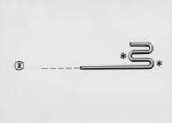
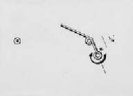
Helical Coil Spring (Figure 35)
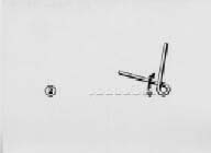
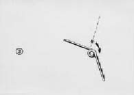
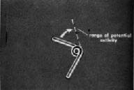
The helical coil spring is another example of a free-ended spring. Its purpose is for mesial or distal tooth movement after teeth have drifted into an edentulous area. (Figure 36) Figures 37 through 40 illustrate the construction of a typical anterior helical coil spring. In order to activate this finger spring, the clinician needs to bend the anterior portion of the spring to its range of potential activity, which is usually one-half the mesio-distal distance of the tooth to be moved, in the direction of the desired tooth movement. (Figures 41 and 42)
Accessory Spring
An accessory spring is one which is attached to the main arch or element of an orthodontic baseplate. Usually, an accessory spring is used to accomplish relatively minor tooth movement along with the primary treatment procedures. A good example of the use of an accessory spring is to “tuck-in” a labially displaced canine tooth or guiding teeth into the dental arch as they erupt. (Figures 43 and 44)
 |
 |
| Figure 25. Hawley wire lies on the middle 1/3 of incisors. | Figure 26. Hawley labial wire with canine loops. |
 |
 |
| Figure 27. Mattress spring to advance upper lateral incisor. | Figure 28. Wire on top of mattress spring to keep it on the cervical portion of the tooth when activated. |
 |
 |
| Figure 29. In combination with the Hawley wire, a mattress spring can help rotate a tooth. | Figure 30. First bend of mattress spring is made with the conical beak of the #139 pliers. Width of finger spring is about the same as that of the tooth to be moved. |
 |
 |
| Figure 31. Each consecutive bend is similar to the first, keeping the entire spring in the same plane. | Figure 32. The retentive portion of the spring should be of sufficient length to be embedded in the palatal acrylic. |
 |
 |
| Figure 33. In order for the spring to be active, the legs should be compressed together prior to placement against the tooth to be moved. | Figure 34. The compressed legs of the mat-tress spring exert a labial force on the lateral incisor. |
 |
 |
| Figure 35. Helical coil spring to move a central incisor toward the midline. | Figure 36. Two helical loop springs can be constructed from the same wire when adjacent teeth have encroached into an extraction space. |
 |
 |
| Figure 37. The helical loop spring construction is begun by bending the 0.022" wire with the conical beak of a #139 pliers. | Figure 38. The second bend is made so that the legs make a right angle with each other. |
 |
 |
| Figure 39. The retentive leg of the spring is bent so that an obtuse angle is made with the active portion. | Figure 40. The retentive leg is completed by bending the end in a circular manner, which is then embedded into the palatal acrylic. |
 |
 |
| Figure 41. The range of potential activity of the helical loop spring extends approximately to the midpoint of the mesio-distal dimension of the tooth to be moved. | Figure 42. As the helical loops unwind, the central incisor will move to the mesial and the canine to the distal to open the space for the missing lateral. |
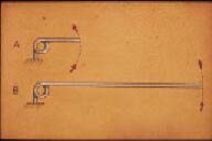
In discussing how to plan anchorage, the importance of such physical laws as action-reaction was stressed. It will also help the clinician to know other features of the mechanical action involved. For example, much depends on the physical properties of the wire used.
The properties of the free-ended and accessory springs are those of hard polished stainless steel round wire. Within certain limits, the same force may be exerted by a thick wire as by a thin one. The difference is due to the degree of deflection needed to produce the force. (Figure 45) Also, due to the greater range of action, a longer spring will move a tooth a greater distance than a short spring.
In orthodontic therapy, the properties required are generally those of a long spring, but this is frequently inconvenient because of the limited space that is available. This disadvantage is overcome by disposing some of the surplus length of wire in the form of a coil. (Figure 46) The coil has the effect of increasing the flexibility of the spring without increasing the length of the arm.
 |
 |
| Figure 43. An accessory spring soldered to a Hawley wire to “tuck- in” a labially displaced premolar. | Figure 44. Accessory springs to guide the eruption of the maxillary lateral incisors. |
 |
 |
| Figure 45. The thin wire A) must be deflected more than the thick wire B) to produce the same amount of force. | Figure 46. The introduction of a coil at the point of attachment of the arm has the effect of increasing the flexibility or range of the spring without increasing the length of the arm; a) represents the arm, b) the coil, and c) the tag. |
 |
 |
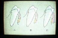
| Figure 47. Arrows show different motions resulting from slightly different points of contact of the springs. In A) the premolar will move toward the distal-buccal, in B) it will move in a buccal direction only. | Figure 48. Because of the difference of the length of the arms, B) has a straighter vector force than A). |
 |
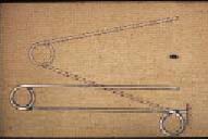 |
| Figure 49. Because of the longer arm, A) will move the tooth in a straighter path than will the shorter arm B). | Figure 50. An additional coil and arm incorporated in a spring in order to increase the range of action. |
 |
 |
| Figure 51. A compensatory bend incorporated in the arm of a finger spring to avoid adjacent teeth during treatment. | Figure 52. The coil is placed on the imaginary perpendicular bisector which is drawn to another imaginary line (left) that connects the present and desired position of the malposed tooth. |
 |
|
| Figure 53. Coil should be placed as far from the point of tooth contact as possible in order to produce maximum range of force and a straighter path of tooth movement. |
There are certain points to remember when using removable appliances for limited orthodontic treatment.