| Contents | Post-Test |
A diagnostic biomechanical analysis of the forces that produce periodontal pathology should precede treatment planning. The restorative procedures are then designed specifically to counteract these traumatic stresses. Tooth mobility cannot be evaluated properly unless its etiology as well as the prognosis for its successful treatment is known. The direction and relative degree of' mobility in comparison with adjacent and contacting teeth are of primary importance in order to evaluate the need for multiple abutments. It should be emphasized that occlusal trauma is only one factor in periodontal disease.
Edema, when associated with occlusal trauma and the inflammatory process of periodontal disease, can contribute to mobility. It can be evaluated by comparing the degree of soft tissue involvement in relation to alveolar bone height and root anatomy. When mobility exists primarily due to occlusal trauma rather than alveolar bone loss, reevaluation should follow periodontal treatment. With the elimination of edema and occlusal trauma, these teeth usually tighten, reducing the need for many restorative procedures.
Tooth mobility often occurs in relation to habits and/or deflective occlusal contact. Bruxism can be initiated by emotional tension as well as local causes. The vast majority of patients show signs of eccentric tooth contact as evidenced by wear facets. It is essential to equilibrate or restore harmonious eccentric positions. Nail biting, pipe chewing, and other such habits can produce occlusal trauma and mobility.
A distinction should be made between senile alveolar atrophy and alveolar bone loss associated with more rapid periodontal disease. The prognosis of senile alveolar atrophy is usually more favorable. When the alveolar bone loss is due to rapid periodontal disease, restorative treatment is designed to support and maintain the existing bone level and to prevent further periodontal alveoloclasia.
Tooth mobility is evaluated in relation to its etiology, treatment, and prognosis. The biomechanical resultant forces on the teeth are produced by the combination of the axial inclination and the "impact area" (angulation of the contacting tooth inclines). When the resultant forces exceed the physiologic tolerance, as evidenced by periodontal pathology, the prosthesis should be designed to counteract these destructive stresses.
Miller's classification of mobility (Classes I to III) is an important aid in evaluating mobility. Root anatomy, location of the periodontal pathology, direction of occlusal trauma, local irritants, and resistance affect tooth mobility. If a tooth is mobile in more than one direction, naturally its prognosis is less favorable. However, if the tooth is mobile in only one direction, the contemplated splint should be of such design that movement in that direction is adequately resisted by healthy alveolar bone of the other abutments.
A relatively mobile tooth is subjected to more stress from a very firm opposing tooth or implant than from an equally mobile antagonist. The unequal mobility of abutments surrounding an edentulous space requires much thought and evaluation before reconstruction is planned. The problem is simple as long as the more mobile tooth is not the terminal abutment. Adequate splinting of firm teeth mesial and distal to the more mobile tooth is usually sufficient.
A biomechanical analysis relates the physical forces to the physiologic environment in which they occur. The purpose of this analysis is to provide a rational basis for specifically designing a splint to ensure maximum alveolar support to resist the forces that will be exerted on it. Five essential factors are analyzed and related to each other. They are the direction of occlusal force, axial inclination, impact area (cuspal incline relationship), resultant line of force, and arch form.
Occlusal force produces vertical and horizontal components that should be analyzed separately. Each of these component forces must be related to the axial inclination, the impact area, and to the specific arch form of the splint. When the splint is designed to counteract both of these components (vertical & horizontal), the alveolar support will successfully withstand any resultant direction of occlusal force.
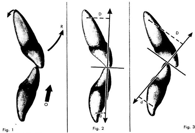
The axial inclination of a tooth is a critical factor in determining the biomechanical forces exerted on its alveolar support. For example, the labial axial inclination of the maxillary incisor teeth places the incisal edge much more labially than its alveolar support. Occlusal force (O) on the incisal edge causes it to rotate labially (R) about the fulcrum, which is located in the area of the apical third of the tooth (Fig. 1). When there is alveolar bone loss, the lever arm is longer. In this case, the remaining weak periodontal support must tolerate more stress than if the normal alveolar height I were present. The mesial axial inclinations of the posterior teeth, as well as their buccal and lingual inclinations, must likewise be related to their respective periodontal support.
The occlusal impact area of the opposing cuspal inclines has a specific angulation. The individual cuspal incline relationship of the occlusal impact area has vital significance. The resultant line of force is perpendicular to the inclination of the occlusal impact area (Fig. 2).
The effect of the resultant force on the periodontal support can be evaluated by relating the axial inclination of the tooth itself with the direction of the resultant line of force from the impact area. For example, due to the axial inclination of the anterior teeth, occlusal pressure usually results in less torque on the lower teeth than on the upper teeth. The direction of force is perpendicular to the contacting inclines The angles of the inclines change in relation to the vertical and horizontal overlap (Figs. 2 & 3).
The resultant line of force usually falls closer to the center of rotation of the lower teeth (d, Figs. 2 & 3) than on the upper teeth (D, Figs. 2, & 3). The direction of the resultant line of force (Arrows), changes depending on the inclination of the impact area caused by the relationship of the vertical and horizontal overlap. As a result of the inclination of the impact area, there is usually more torque on the maxillary anterior teeth than on the mandibular anterior teeth.
When the teeth are splinted; the abutments, roots, and splint become as one solid object, with a center of rotation controlling motion in each plane. The amount of lateral torque exerted on the alveolar support is directly related to the distance between the resultant line of force and the center of rotation of the splint. The closer the resultant line of force is to the center of rotation of the splint, the less the torque, due to the shorter lever arm.
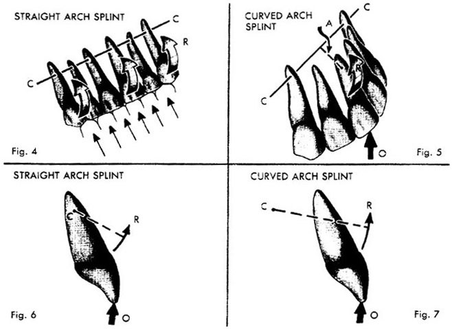
Due to the axial inclination, evenly distributed vertical component force on a maxillary straight arch anterior splint can cause the whole splint to rotate (R) about the center of rotation (CC), passing through the area of the apical third of all the teeth (Fig. 4). The resultant line of force on each tooth in the splint is quite similar to that created by the occlusal pressure on an unsplinted tooth (Figs. 1 & 2). However, it is true that vertical occlusal pressure applied to only one area of the splint, will distribute that force disproportional to all the remaining teeth, relative to the location of the original force application. However, the effect of the vertical occlusal pressure applied over the entire splint is almost as damaging as if there were no splint. (Subsequently discussed)
|
|
| Legends |
Fig. 1. Axial inclination. Occlusal force (O) on the incisal edge of the maxillary incisor causes it to rotate labially (R) about the fulcrum, which is located in the area of the apical third of the tooth.
Fig. 2. Impact area. The occlusal impact area of the opposing cuspal inclines has a specific angulation. The resultant line of force is perpendicular to the inclination of the occlusal impact area.
Fig. 3. Resultant line of force. The direction of the resultant line of force is perpendicular to the contacting inclines. This line of force usually falls closer to the center of rotation of the lower teeth (d) than on the upper teeth (D).
Vertical occlusal pressure on a maxillary anterior curved arch splint presents completely different force picture than a straight arch. As shown in Fig. 4, vertical occlusal force on a straight arch splint causes the whole unit to revolve around the center of rotation (CC) running through the area'of the apical third of each tooth; this causes a rotation movement. By comparison, pressure on the central incisor (O, Fig. 4) of a curved arch splint would cause the center of rotation (CC) to pass near the apical third of the canine teeth (distal abutments) (Fig. 5). All the remaining teeth would have to move around this center of rotation.
Due to the curve in the arch, the central and lateral incisors would be anterior (A, Fig. 5) to the center of rotation (CC). This causes a change in the direction of the force application to the alveolar bone, which is now more vertical than the rotation that occurs when the teeth are arranged in a straight arch. In Fig. 6 this point is illustrated; a proximal view of only the central incisor is shown for clarity. Vertical occlusal pressure (O, Fig. 6) in the straight arch form results in a more lateral rotation (R) due to the center of rotation within the tooth (C). In a curved arch splint the center of rotation is located posteriorly (C, Fig. 7), which results in a more apical rotation (R) of the force exerted on the alveolar support.
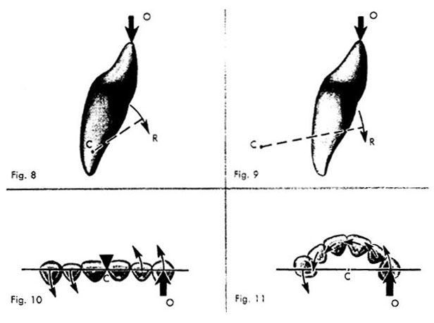
Similar conclusions will be obtained when analyzing the forces distributed to the alveolar support with a straight or curved arch mandibular anterior splint. The proximal view of only a central incisor illustrating these types of splints is shown in Figs. 8 and 9. In a straight arch the center of rotation (C, Fig. 8), of the splint passes through the apical third of the abutments. Vertical occlusal pressure (O, Fig. 8) results in a more lateral rotational force (R) exerted on the alveolar support.
When the arch of the splint is curved, the center of rotation passes through the apical third of the distal abutments (CC, Fig. 9) In relation to the central incisor, the
 |
| Legends |
Fig. 4. Vertical component force, straight arch splint: Due to the labial axial inclination of the maxillary anterior teeth, evenly distributed vertical component force on a straight arch anterior splint can cause the whole splint to rotate (R) about the center of rotation (CC), passing through the area of the apical third of the teeth.
Fig. 5. Vertical component force, curved arch splint: Vertical component force on the central incisor (O) of a curved arch maxillary splint would cause the center of rotation (CC) to pass near the apical third of the canine teeth (distal abutments). All the remaining teeth would have to move around this center of rotation.
Fig. 6. Straight arch splint: A proximal view of only the central incisor is shown for clarity. Vertical occlusal pressure (O) in the straight arch splint results in a rotation movement (R) due to the center of rotation (C) within the tooth.
Fig. 7. Curved arch splint: In a curved arch splint the center of rotation is located posteriorly (C). Vertical occlusal pressure (O) results in a more apical direction of the force (R) exerted on the alveolar support center of rotation is located lingually (C). Vertical occlusal pressure (O, Fig. 9) results in a more apical direction of force (R) exerted on the alveolar bone support.
When horizontal component force is applied to the canine (0, Fig. 10), the splint helps protect this tooth by force distribution to the remaining teeth. The splint will tend to rotate horizontally (parallelto the plane of occlusion) about the center of rotation (C), which is located near the midline. The opposite canine will have a lingual pressure applied to its supporting bone. The remaining teeth will distribute a labial or lingual pressure, depending on which side of the center of rotation they are located, as in Fig. 10. The variations in each case preclude exact pinpoint location of the center of rotation. The approximate location of the center of rotation is all that is necessary for our purposes.
Horizontal component force on the canine (O, Fig. 11) of a curved arch splint initiates a horizontal rotation with the center of rotation (C) on a line passing approximately through the apical third of the distal (canine) abutments. Due to the arch curvature, this center of rotation is posterior to the central incisors. The curved arch form changes the direction of forces considerably from that seen when we have a straight arch splint (Fig. 10). When we review the horizontal rotation in the straight arch splint, we find labial forces on the side of force application and lingual forces on the opposite side. Horizontal component force on the canine of a curved arch splint causes a horizontal rotation about the center of rotation (C, Fig. 11). Instead of labial or lingual forces on the abutments, as in the straight arch splint (Fig. 10), we now have more favorable forces in the mesiodistal direction (Fig. 11). These forces tend to push the teeth bodily through bone, in contrast to the lateral labiolingual force in the straight arch splint (Fig. 10).
 |
| Legends |
Fig. 8. Mandibular straight arch splint: The proximal view of only a central incisor is illustrated. The center of rotation (C) of the splint passes through the apical third of the abutments. Vertical occlusal pressure (0) on such a splint results in a lateral rotational force (R) exerted on the alveolar support.
Fig. 9. Mandibular curved arch splint: The proximal view of only a central incisor is illustrated. The center of rotation passes through the apical third of the distal abutments. In relation to the central incisor the center of rotation is located posteriorly (C). Vertical occlusal pressure (O) results in a more apical direction of force (R) exerted on the alveolar support.
Fig. 10. Horizontal component force: straight arch splint: When horizontal component force is applied to the canine (O), the splint will tend to rotate horizontally (parallelto the plane of occlusion) about the center of rotation (C), which is located near the midline.
Fig. 11. Horizontal component force in a curved arch splint: Horizontal component force on the canine (0) of a curved arch splint initiates a horizontal rotation with the center of rotation (C) ön a line passing approximately through the apical third of the two canines. This produces more favorable forces in the mesiodistal direction.
The character of the anterior impact area is produced by the relative horizontal and vertÌcaloverlap of the anterior teeth. The appropriate term for this anterior incline relationship is called the incisal guidance. Subsequent descriptions will deal with the clinical application of incisal guidance planning for periodontal health.
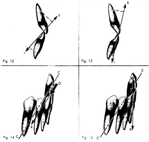
Since the resultant line of force is perpendicular to the inclination of the impact area, the overlap relationship affects the amount of torque distributed to the periodontal support. In a relatively steep vertical overlap due to the axial inclination of the teeth, the resultant line of force passes at a greater distance from the alveolar support of the upper tooth (R) than the lower tooth (r, Fig. 12). This produces more torque on the maxillary than on the mandibular teeth.
With a relatively shallow vertical overlap, the resultant line of force (R, Fig. 13) passes closer to the alveolar support, usually producing less lateral torque. Due to the axial inclination of the lower teeth, the resultant line of force may shift from the lingual direction, as in the steep overlap (R, Fig. 12), to the labial direction, as in the shallow overlap (R, Fig. 13). The conclusion can be drawn that in both deep and shallow vertical overlap, the lower anterior teeth are usually favored over the upper teeth. The torque is greater on the maxillary teeth because the resultant line of force produced by the impact area falls at a greater distance from the center of rotation (or alveolar support) than on the mandibular teeth (Figs. 12 and 13).
Understanding the direction of the resultant line of force, as just described, is of practical value only when it is related to the center of rotation of the splint itself. The location of the center of rotation of the splint depends on the specific arch form. When the resultant line of force passes through the center of rotation, no torque or lateral force is exerted on the periodontal support. For example, a door will open on its hinge (center of rotation) only when a force is applied at an angle to the hinge. If a force directed toward the hinge is applied against the door's edge, the door will not move.
 |
| Legends |
Fig. 12. Anterior impact area, steep vertical overlap: In a relatively line of force steep vertical overlap the resultant passes at a greater distance from the alveolar support of the upper tooth (R) than the lower tooth (r). This produces more torque on the maxillary than on the mandibular teeth.
Fig. 13. Anterior impact area, shallow vertical overlap: With a relatively shallow vertical overlap, the resultant line of force (R, r) passes closer to the alveolar support, usually producing less torque.
Fig. 14. Mandibular curved arch splint, deep vertical overlap: When a mandibular curved arch splint has a fairly deep vertical overlap (O), little torque is produced because the resultant line of force (R) is directed lingually toward the center of rotation of the splint (CC).
Fig. 15. Mandibular curved arch splint, shallow vertical overlap: If the same splint had a shallow vertical overlap (O), the resultant line of force (R) would pass at a greater distance from the center of rotation (CC), producing more torque and stress on the alveolar support.
When a mandibular curved arch splint has a fairly deep vertical 14), little overlap (O, Fig. torque is produced because the resultant line of force (R) is directed lingually toward the center of rotation of the splint (CC, Fig. 14). If the same splint had a shallow vertical overlap (O), the resultant line of force (R) would pass at a greater distance from the center of rotation (CC), producing more torque and stress on the alveolar support (Fig. 15). The resultant torque on anterior splinted teeth most often favors the lower arch at the expense of the upper arch. Therefore, careful diagnostic analysis should always precede clinical procedures.
When splinting periodontally involved anterior teeth, a straight arch form usually does not afford as favorable a prognosis as a curved arch form. In a natural dentition there is usually more torque on the upper than on the lower anterior teeth. This is true whether there is a fairly deep or shallow vertical overlap. The deeper the vertical overlap the more stress is exerted on the upper than on the lower arch. The conclusion can be drawn that, with the same degree of periodontal loss, the maxillary arch usually requires more extensive splinting than the mandibular arch.
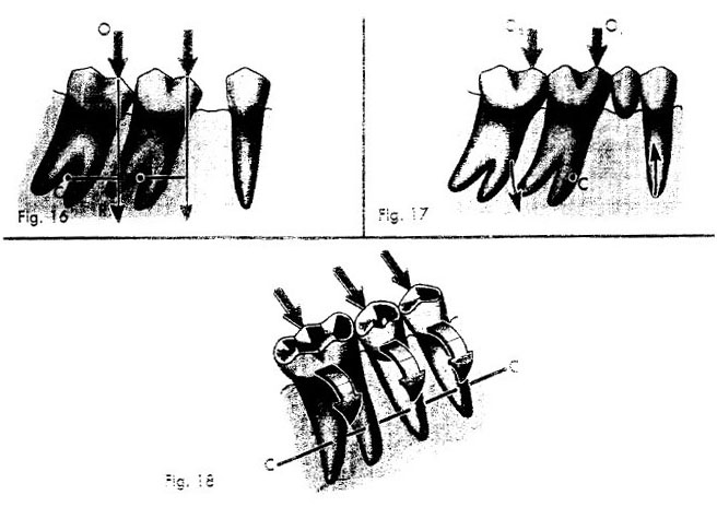
We should consider the effect of occlusal forces on posterior tilted teeth. Occlusal force (O, Fig.16) in the central fossa of a tilted molar falls mesially (R) to the center of rotation (C, Fig. 16). This creates mesial torque, driving the teeth still more mesially. Restoring the missing premolar and splinting the remaining molars change the force exerted on the periodontal support. The center of rotation (C, Fig. 17) of the completed restoration may be somewhere
within the root area of the first molar in the apical third. Occlusal pressure (Oi, Fig. 17) in the central fossa of the first molar may fall close to the center of rotation, creating little torque. Occlusal pressure (O2, Fig.17) in the fossa of the second molar creates torque about the center of rotation (C). Due to the geometric location of the center of
 |
| Legends |
Fig. 16. Axial inclination: Occlusal force (O) in the central fossa of a tilted molar falls mesially (R) to the center of rotation (C).
Fig. 17. Restored teeth: The center of rotation (C) of the completed restoration may be somewhere within the root area of the first molar in the apical third. Occlusal pressure (Oi) in the central fossa of the first molar may fall close to the center of rotation, creating little torque. Occlusal pressure (O2) in the fossa of the second molar creates torque about the center of rotation (C).
Fig. 18. Mandibular straight arch splint: When the teeth of a mandibular straight arch are splinted, the center of rotation (CC) passes through the apical third of all teeth. Occlusal force on the buccal slope of a lower tooth produces a lingual rotation effect on all the teeth about the center of rotation (CC). rotation, this compressive force is more in line with the long axis of the second molar. The premolar is pulled occlusally in line with its long axis. We see that splinting tilted teeth decreases the stresses and changes the direction of the forces to the periodontal support. These force changes help increase the physiologic resistance of the periodontal structures.
When the teeth of a mandibular straight arch are splinted, the center of rotation passes through the apical third of all the teeth. Occlusal force on the buccal slope of alower molar produces a resultant force perpendicular to that incline which is in the lingual direction. If the teeth in a straight arch were splinted, this type of force would have a lingual tilting effect on all the teeth (Fig. 18). The abutments would have a tendency to rotate lingually about the center of rotation (CC), which passes through the apical third of the roots. Clinically, this is observed often with three unit bridges that are very firm to vertical, mesial, and distal forces but have clinical mobility buccolingually.
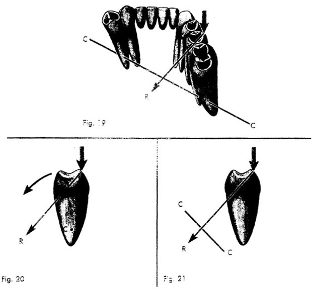
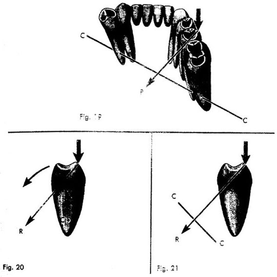
If the splint goes around a curve in the arch, a great mechanical advantage is obtained, especially in the lower jaw. The center of rotation (CC, Fig. 19) usually passes near the apical third of the terminal abutments. A resultant lingual force (R, Fig. 19) from the buccal slope of a posterior tooth may pass through or near the center of rotation, causing little or no torque. The force to the periodontal support would be compression on one side of the roots and tension on the other, with very little rotation. It is obvious that the more extended the curve in the arch, the farther the center of rotation is moved lingually. Much more lateral force can be tolerated on the lower arch physiologically, because of this three-dimensional relationship.
In Figs. 20 and 21 only the premolar of each type of splint is illustrated. The premolars are shown from the proximal view in relation to the center of rotation. In the straight arch splint the resultant force (R, Fig. 20) causes lingual torque because the
 |
| Legends |
Fig. 19. Mandibular curved arch splint: The center or rotation (CC) usually passes near the apical third of the terminal abutments. A resultant lingual force (R) from the buccal slope of a posterior tooth may pass through or near the center of rotation, causing little or no torque.
Figs. 20 and 21. Comparison of torque in mandibular straight and curved arch splints: Only the premolar of each type of splint is illustrated. The premolars are shown from the proximal view in relation to the center of rotation. In the straight arch splint the resultant force (R, Fig. 20) causes torque because the center of rotation (C) passes through the apical third of the roots. In the curved arch splint the center of rotation (CC, Fig. 21) is lingual to the tooth, the resultant force (R) passes lingually through or near the center of rotation, producing little or no torque.
 |
| Legends |
Fig. 19. Mandibular curved arch splint: The center or rotation (CC) usually passes near the apical third of the terminal abutments. A resultant lingual force (R) from the buccal slope of posterior tooth a may pass through or near the center of rotation, causing little or no torque.
Figs. 20 and 21. Comparison of torque in mandibular straight and curved arch splints: y the premolar of each type of splint is illustrated. The premolars are shown from the xintal view in relation to the center of rotation. In the straight arch splint the resultant force Fig. 20) causes torque because the center of rotation (C) passes through the apical third of the . In the curved arch splint the center of rotation (CC, Fig. 21) is lingual to the tooth, the t force (R) passes lingually through or near the center of rotation, producing little or no center of rotation (C, Fig. 20) passes through the apical third of the roots. Since the center of rotation (CC, Fig. 21) of the curved arch splint is lingual to the tooth, the resultant force (R) passes lingually through or near the center of rotation, producing little or no torque. Thus, due to the design of a curved arch splint, a laterally inclined lingual force can produce little or no torque.
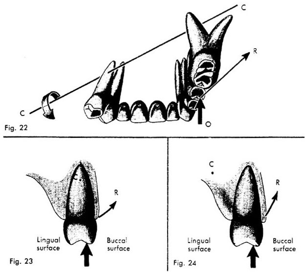
The effect of occlusal pressure on the maxillary straight arch splint is similar to the mandibular straight arch splint (Fig. 20). The direction of the resultant force in the maxillary splint usually is buccal (Fig. 22), whereas in the mandibular splint it is most often lingual in direction.
For comparison purposes, a splint from the 2nd premOlar on one side to the inolar of the opposite side (Fig. 22) will be discussed. This restoration involves the same teeth as the previously described mandibular splint (Fig. 19). The center of rotation (CC, Fig 22) usually passes near the apical third of the terminal abutments. It is extremely important to consider that the same occlusal force that created little or no torque on the lower jaw now creates a great deal of torque on the upper jaw. As seen in Fig. 22, this resultant force is buccal in direction, while the center of rotation is lingual to the tooth. This results in a great deal of torque (lateralforce) on the maxillary restoration.
In summary, the maxillary restoration distributes more torque to its supporting bone since the resultant line of force from the occlusal impact area falls at a greater distance from the center of rotation (Fig. 22). By comparison, in the mandibular restoration this line of force falls close to the center of rotation, creating little or no torque (Fig. 19).
Proximal views of only the premolar teeth from each type of maxillary splint have been illustrated in relation to their centers of rotation (C, Figs. 23, & 24). The straight arch splint tends to rotate about its center of rotation (C, Fig. 23), which is located in the
 |
| Legends |
Fig. 22. Maxillary curved arch splint: This restoration involves the same teeth as the previously described mandibular splint. The center of rotation (CC) usually passes near the apical third of the terminal abutments. Occlusal force (O) produces a resultant force (R) which is buccal in direction, while the center of rotation is lingual to the tooth.
Figs. 23 and 24. Comparison of torque in maxillary straight and curved arch splints: Proximal views of only the premolar tooth from each type of maxillary splint have been illustrated in relation to their centers of rotation (C). The straight arch splint tends to rotate about its center of rotation (C, Fig. 23), which is located in the apical third area of the roots. The resultant force (R) distributed to the alveolar support is lateral in direction. By comparison, the center of rotation (C, Fig. 24) of the curved arch splint is located lingually. This distributes the\ resultant force (R, Fig. 24) to the periodontal support more apically than in the straight arch splint. apical third area of the roots. The resultant force (R, Fig. 23) distributed to the alveolar support is lateral in direction. By comparison, the center of rotation (C) of the curved arch splint is located lingually (Fig. 24). This distributes the resultant line of force (R, Fig. 24) to the periodontal support more apically than in the straight arch splint.
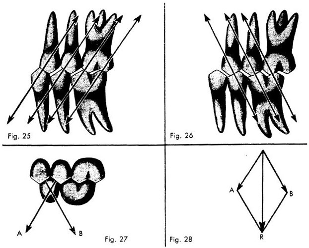
The occlusal impact area must also be considered during eccentric movements of the mandible. In mastication the teeth do not always penetrate the bolus. Some practitioners maintain that only during deglutition is there tooth contact, whereas others show evidence supporting the view that there is contact during mastication. My evidence indicates only that there definitely is eccentric tooth-to-tooth contact, which is the important factor rather than when it occurs. In lateral eccentric movements, if the distal inclines of the lower teeth articulate with the mesial inclines of the upper teeth (Fig. 25), the lower teeth will have a mesial component of force exerted on them.
When the mesial inclines of the lower teeth and the distal inclines of the upper teeth contact in lateral eccentric movements, distal torque on the lower teeth develops (Fig. 26). In both cases it is important to point out that any break in the interproximal contact will allow a severe torque to be applied to the tooth involved. If both mesial and distal inclines are in contact in lateral eccentric movements, the mesial and distal components (A,B, Fig. 27), tend to cancel each other producing a vertical resultant force (R, Fig. 28). A deflective occlusal contact concentrates the power of the musculature in one area, producing tremendous torques.
A force analysis of some of the factors involved in splinting periodontally involved teeth allows us to draw the following conclusions. The differences in force distribution between maxillary and mandibular splints require a different evaluation and recommendation with relatively the same degree of periodontal involvement. Most often the maxilla requires more extensive splinting than the mandible. The ability of tilted teeth to withstand occlusal stress is generally improved with the construction of a fixed partial prosthesis.
 |
| Legends |
Fig. 25. Eccentric cuspal contact: In lateral eccentric movements, if the distal inclines of the lower teeth articulate with the mesial inclines of the upper teeth, the lower teeth will have a mesial component of force exerted on them, while the maxillary teeth have a distal component of force.
Fig. 26. Eccentric cuspal contact: When the mesial inclines of the lower teeth and the distal inclines of the upper teeth contact in lateral eccentric movements, distal torque on the lower teeth develops and mesial torque on the upper teeth.
Fig. 27. Component forces: If both mesial and distal inclines are in contact in lateral eccentric movements, the mesial and distal components (A and B) tend to cancel each other.
Fig. 28. Resultant force: Mesial and distal component forces (A and B) tend to cancel each other by forming the vertical resultant force (R).
Every rigid dental casting, from a simple full cast crown to a large multiple-unit bridge, has a path of insertion toward its final seat. Every surface of each abutment, as well as all the upright surfaces of every abutment in relation to each other, must be convergent to the path of insertion of the fabricated restoration. As a general guide the contra-angle hand piece can be kept parallel to the general plane of occlusion. The taper of the instruments used will create enough convergence to allow complete seating of the restoration. This is an oversimplification but a practical starting point.
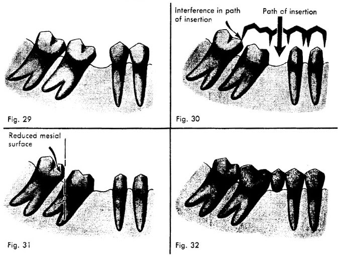
When the posterior molars are tilted anteriorly (Fig. 29), the mesial surface of the enamel will be anterior to the distal root surface of the anterior adjacent tooth. The mesial surface of the adjacent unprepared tooth can interfere in the planned path of insertion of the fabricated restoration (Fig. 30).
In this case, the mesial surface of the adjacent unprepared tooth should be reduced or restored so that its mesial surface allows clearance for the distal margin of the restoration during insertion (Fig. 31). This step should be completed before final impressions are obtained in order to ensure a proper contact point of the finished restoration with the adjacent unprepared tooth (Fig. 32).
Occasionally, due to periodontal disease or caries, exaggerated proximal depth of the preparation is required. When the posterior unprepared tooth is tilted mesially, reduction of its mesial surface to allow for insertion of the restoration would cause pulpal Interference in path Path of insertion of insertion
 |
| Legends |
Fig. 29. Adjacent unprepared teeth. When the posterior molars are tilted anteriorly, the mesial surface of the enamel will be anterior to the distal root surface of the anterior adjacent tooth.
Fig. 30. Interference in path of insertion. The mesial surface of the adjacent unprepared tooth can interfere in the planned path of insertion of the fabricated restoration.
Fig. 31. Adjacent tooth corrected. The mesial surface of the adjacent unprepared tooth should be reduced or restored so that its mesial surface allows clearance for the distal margin of the restoration during insertion.
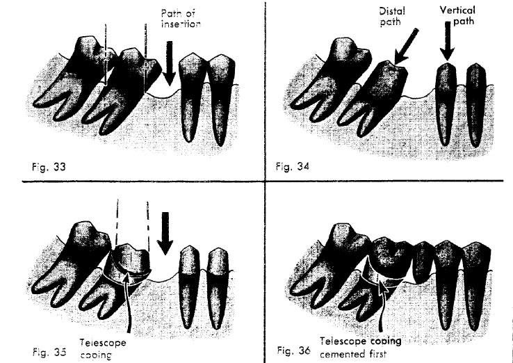
Fig. 32. Finished restoration. Proper contact point of the fmished restoration with the adjacent unprepared tooth. exposure (Fig. 33). Mesial reduction of the prepared tooth, parallel to the path of insertion, would also endanger the vitality of the abutment.
The tilted abutment is prepared paralle) to its long axis; the distal path of insertion for the casting permits the most conservative reduction of tooth structure (Fig. 34). The remaining abutments are prepared with the usual vertical path of insertion for the final restoration. The telescope coping is prepared with a high distal shoulder that permits the machining of the outer surface to be made parallel to the anterior path of insertion of the completed restoration (Fig. 35).
The superstructure casting, which fits over the telescope coping, is fabricated and assembled with the anterior segment of the bridge. To ensure a good fit of the superstructure casting over the telescope coping, the coping shoulders should have an accessory bevel. The telescope coping is cemented on the molar abutment first. The completed restoration is then cemented to the telescope coping and anterior abutments as Path o Distal Vertical
 |
| Legends |
Fig. 33. Exaggerated proximal depth. Occasionally, exaggerated proximal depth of the preparation is required. When the posterior unprepared tooth is tilted mesially, reduction of its mesial surface to allow for insertion of the restoration would cause pulpal exposure.
Fig. 34. Telescope coping technique. The tilted abutment is prepared parallel to its long axis; the distal path of insertion for the casting permits the most conservative reduction of tooth structure. The remaining abutments are prepared with the usual vertical path of insertion for the final restoration.
Fig. 35. Parallelism. A telescope coping is prepared with a high distal shoulder that permits the machining of the outer surface to be made parallel to the anterior path of insertion of the completed restoration.
Fig. 36. Cementation. The telescope coping is cemented on the molar abutment first. The completed restoration is then cemented to the telescope coping and anterior abutments as usual.
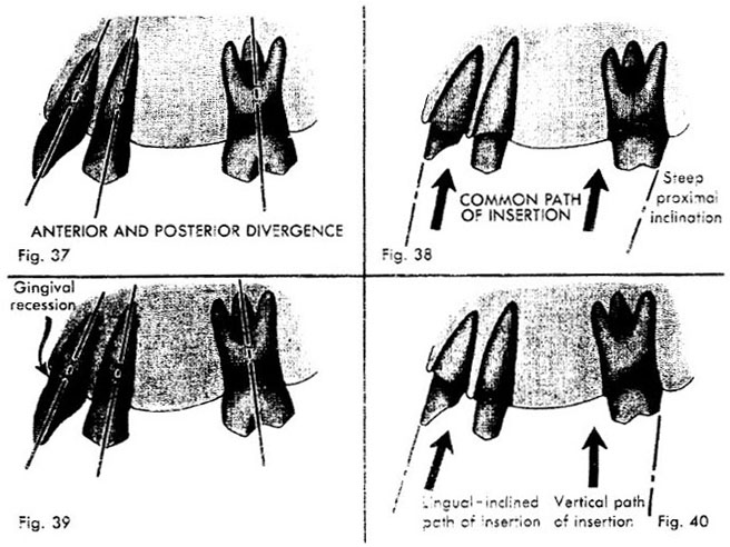
In large-span bridge construction, due to anterior labial axial inclination and the anteroposterior curve of occlusion, the abutments may diverge (Fig. 37). A common path of insertion can be obtained by slightly exaggerating the inclination of the distal proximal reduction of the posterior abutments (Fig. 38).
The usual anterior and posterior divergence can be exaggerated by labial gingival recession (Fig. 39). When this occurs the anterior preparations usually require a more lingual path of insertion in order to provide an esthetic restoration (Fig. 40). The posterior abutments are prepared with the usual vertical path of insertion. When the first bicuspid is in position, it is prepared parallel to the anterior path of insertion.
 |
| Legends |
Fig. 37. Anterior and posterior divergence: In large-span bridge construction, due to anterior labial axial inclination and the anteroposterior curve of occlusion, the abutments may diverge.
Fig. 38. Parallelism: A common path of insertion can be obtained by slightly exaggerating the inclination of the distal proximal reduction of the posterior abutments.
Fig. 39. Exaggerated labial axial inclination: The usual anterior and posterior divergence can be exaggerated by labial gingival recession.
Fig. 40. Divergent paths of insertion: When this occurs, the anterior preparations usually require a more lingual path of insertion in order to provide an esthetic restoration. The posterior. abutments are prepared with the usual vertical path of insertion.
A telescope coping for the first bicuspid is waxed up with the adjacent canine of the anterior segment and cast in one piece. The outer surface of the telescope coping is machined parallel to the path of insertion of the posterior segment. The superstructure casting is fabricated and assembled to the anterior segment, as previously described (Figs. 33 to 36).
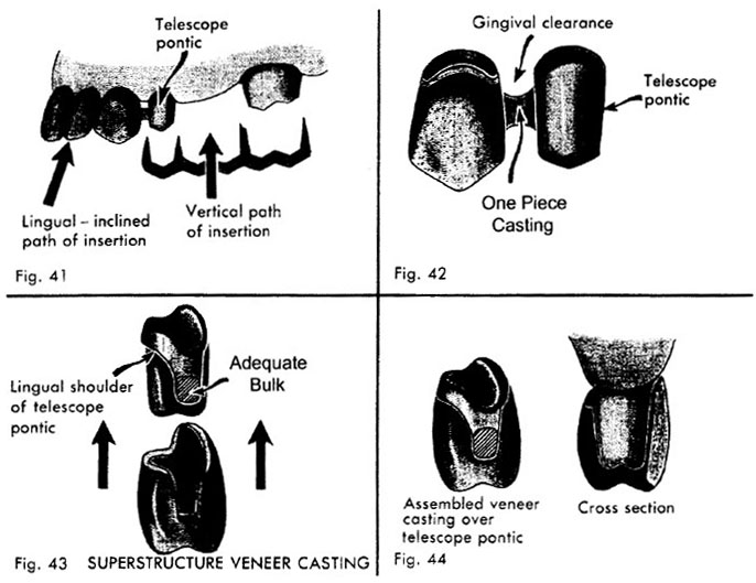
When the first bicuspid is missing, this space is utilized to accommodate the divergence of the paths of insertion of the posterior and anterior segments. A telescope pontic is waxed up and cast with the adjacent anterior coping (Fig. 41). The gingival contour of the telescope pontic should provide adequate gingival clearance (Fig. 42). The telescope pontic is then machined so that its walls are parallel to the path of insertion of the posterior segment (Fig. 41). A lingual shoulder is prepared in the telescope pontic to prevent undue bulk; an accessory bevel on the shoulder is provided to facilitate good adaptation between the telescope pontic and the superstructure casting (Fig. 43). The mesial shoulder extends toward the occlusal surface to provide space for a strong casting and gingival clearance.
To obtain maximum esthetics, it is advisable to have the labial portion of the superstructure veneer contact the gingiva and form part of the saddle (Fig. 44). When the superstructure veneer is seated over the telescope pontic, the gingival portions should be smooth and well contoured for gingival health.
It is advisable to accomplish final cementation in two steps: the segment containing the telescope pontic is always cemented first. The posterior segment, including the superstructure veneer, is subsequently cemented over the telescope pontic. The benefit of either telescope technique is that the biomechanical advantage of a one piece restoration can be obtained when parallelism is not possible.
 |
| Legends |
Fig. 41. Telescope pontic: When the first bicuspid is missing, this space is utilized to accommodate the divergence of the paths of insertion of the posterior and anterior segments. A telescope pontic is waxed up with the adjacent coping and cast in one piece.
Fig. 42. Gingival Clearance: The solder joint attaching the telescope pontic should provide adequate gingival clearance.
Fig. 43. Parallelism established: The telescope pontic is then machined so that its walls are parallel to the path of insertion of the posterior segment.
Fig. 44. Esthetics: To obtain maximum esthethics, it is advisable to have the labial portion of the superstructure veneer contact the gingiva and form part of the saddle.
Deep lug rests, semi-precision, and precision attachments invariably loosen under functional stress. From a biomechanical point of view, each segment functions as an independent unit. The advantages of a curved arch splint are lost unless there is cognplete rigidity of the bridge around the arch.
The problems associated with parallelism should be eliminated by thorough analysis and planning before the abutments are prepared. When one-piece construction is contraindicated, the telescope coping or telescope pontic facilitates the rigid uniting of nonparallel segments of an extensive fixed partial prosthesis.